
User Manual
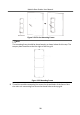
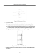
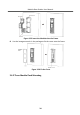
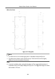
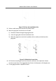
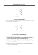
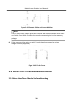
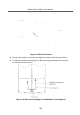
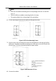
Table Of Contents
- Legal Information
- Symbol Conventions
- Regulatory Information
- 1 Terminal and Wiring
- 2 Installation
- 3 Activation
- 4 Remote Configuration via Web
- 4.1 Live View
- 4.2 User Management
- 4.3 Number Settings
- 4.4 Device Management
- 4.5 Parameters Settings
- 5 Configuration via Client Software
- A. Communication Matrix and Device Command

Figure 2-40 Fix the Gang Box
6.
Fill the gap between the gang box and wall with concrete. Remove the mounng
ears with tool aer concrete is dry.
Figure 2-41 Remove the Mounng Ears
7.
Connect cables and insert the modules.
1) Connect Cable 1 and one end of Cable 2 to the corresponding interfaces of
the main unit, then insert the main unit into the upper grid.
2) Connect the other end of Cable 2 to the input interface of Sub Module 1.
Connect one end of Cable 3 to the output interface of Sub Module 1 and
insert it into the middle grid.
3) Connect the other end of Cable 3 to the input interface of Sub Module 2.
Insert it into the boom grid.
Module Door
Staon User Manual
37