
User Manual
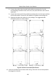
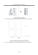
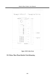
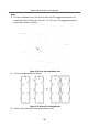
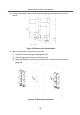
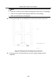
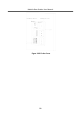
Table Of Contents
- Legal Information
- Symbol Conventions
- Regulatory Information
- 1 Terminal and Wiring
- 2 Installation
- 3 Activation
- 4 Remote Configuration via Web
- 4.1 Live View
- 4.2 User Management
- 4.3 Number Settings
- 4.4 Device Management
- 4.5 Parameters Settings
- 5 Configuration via Client Software
- A. Communication Matrix and Device Command

1) Connect the cables from the wall and module-connecng line 1 to the
corresponding interfaces of the main unit, then place the main unit into the
upper grid.
2) Connect the other end of the module-connecng line 1 to the input interface
of the sub module. Connect all sub modules via module-connecng lines.
3) Organize the cable with cable e in the package. The suggested cable
connecon picture as shown below.
Figure 2-49 Line Connecon Eect Picture
9.
Insert the modules into the frame aer wiring. The main unit must be placed in
the top grid on the le.
Module Door
Staon User Manual
42