
User Manual
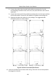
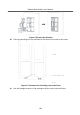
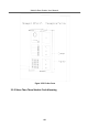
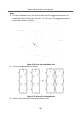
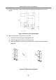
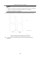
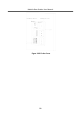
Table Of Contents
- Legal Information
- Symbol Conventions
- Regulatory Information
- 1 Terminal and Wiring
- 2 Installation
- 3 Activation
- 4 Remote Configuration via Web
- 4.1 Live View
- 4.2 User Management
- 4.3 Number Settings
- 4.4 Device Management
- 4.5 Parameters Settings
- 5 Configuration via Client Software
- A. Communication Matrix and Device Command

Steps
1.
Drill the installaon hole, and pull the cable out.The suggested dimension of
installaon hole is 321.8 (W) × 315 (H) × 45.5 (D) mm. The suggested length of
cables le outside is 270 mm.
Figure 2-54 Cave the
Installaon Hole
2.
Connect two gang boxes as below.
Figure 2-55 Connect Two Gang Boxes
3.
Select a cable entry and remove the plasc sheet.
Module Door
Staon User Manual
46