
User Manual
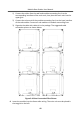
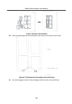
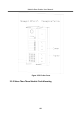
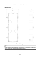
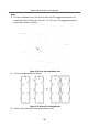
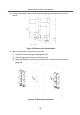
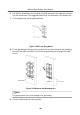
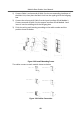
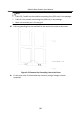
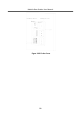
Table Of Contents
- Legal Information
- Symbol Conventions
- Regulatory Information
- 1 Terminal and Wiring
- 2 Installation
- 3 Activation
- 4 Remote Configuration via Web
- 4.1 Live View
- 4.2 User Management
- 4.3 Number Settings
- 4.4 Device Management
- 4.5 Parameters Settings
- 5 Configuration via Client Software
- A. Communication Matrix and Device Command

1) Connect Cable 1 and one end of Cable 2 to the corresponding interfaces of
the Main Unit, then place the Main Unit into the upper grid of the le gang
box.
2) Connect the other end of Cable 2 to the input interface of Sub Module 1.
Connect one end of Cable 3 to the output interface of Sub Module 1 and
insert it into the middle grid of the le gang box.
3) Finish the wiring and inserng according to the cable number and the
posion shown as below.
Figure 2-60 Install Mounng Frame
The cables connect to each module shown as below.
Figure 2-61 Cables Connecon
Module Door
Staon User Manual
49