
User Manual
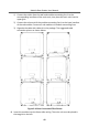
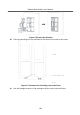
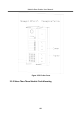
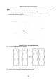
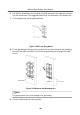
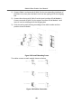
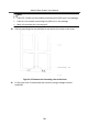
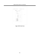
Table Of Contents
- Legal Information
- Symbol Conventions
- Regulatory Information
- 1 Terminal and Wiring
- 2 Installation
- 3 Activation
- 4 Remote Configuration via Web
- 4.1 Live View
- 4.2 User Management
- 4.3 Number Settings
- 4.4 Device Management
- 4.5 Parameters Settings
- 5 Configuration via Client Software
- A. Communication Matrix and Device Command

Note
•
Cable 2,3,5 and 6 are the module-connecng lines (190 mm) in the package.
•
Cable 4 is the module-connecng line (400 mm) in the package.
•
Main unit must be put in the top grid.
10.
Pull the grounding line out and xed its two end to the screw on the cover.
Figure 2-62 Connect the Grounding Line to the Cover
11.
Fix the cover with 2 socket head cap screws by using a hexagon wrench
(supplied).
Module Door
Staon User Manual
50