
User Manual


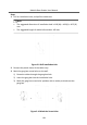


Table Of Contents
- Legal Information
- Symbol Conventions
- Regulatory Information
- 1 Terminal and Wiring
- 2 Installation
- 3 Activation
- 4 Remote Configuration via Web
- 4.1 Live View
- 4.2 User Management
- 4.3 Number Settings
- 4.4 Device Management
- 4.5 Parameters Settings
- 5 Configuration via Client Software
- A. Communication Matrix and Device Command

7.
Connect the cables to the corresponding interfaces of the main unit and insert
the unit into the gang box.
Figure 2-13 Insert the Main Unit
8.
Fix the cover and the main unit with 2 socket head cap screws by using a
hexagon wrench (supplied).
Figure 2-14 Fix the Cover
2.3 Two-Module Installaon
2.3.1 Two-Module Surface Mounng
Module Door Staon User Manual
21