Network Dome Camera ECI-D62Z2 Quick Start Guide
Manual Illustrations and Features Graphics (screen shots, product pictures, etc.) in this document are for illustrative purposes only. Your actual product may differ in appearance. Your product might not support all features discussed in this document. Hikvision USA Inc., 18639 Railroad St., City of Industry, CA 91748, USA • Hikvision Canada, 4848 rue Levy, Saint Laurent, Quebec, Canada, H4R 2P1 Telephone: +1-909-895-0400 • Toll Free in USA: +1-866-200-6690 • E-Mail: sales.usa@hikvision.com • www.hikvision.
CONFORMS THE APPLICABLE LAW. HIKVISION SHALL NOT BE LIABLE IN THE EVENT THAT THIS PRODUCT IS USED WITH ILLEGITIMATE PURPOSES. IN THE EVENT OF ANY CONFLICTS BETWEEN THIS MANUAL AND THE APPLICABLE LAW, THE LATER PREVAILS. Regulatory Information FCC Information Please take attention that changes or modification not expressly approved by the party responsible for compliance could void the user’s authority to operate the equipment.
Safety Instruction These instructions are intended to ensure that user can use the product correctly to avoid danger or property loss. The precaution measure is divided into “Warnings” and “Cautions.” Warnings: Serious injury or death may occur if any of the warnings are neglected. Cautions: Injury or equipment damage may occur if any of the cautions are neglected. Warnings Follow these safeguards to prevent serious injury or death.
● ● ● ● ● ● ● Do not place the camera in extremely hot, cold (the operating temperature shall be -30° to +60° C, or -40° to +60° C if the camera model has an “H” in its suffix), dusty or damp locations, and do not expose it to high electromagnetic radiation. To avoid heat accumulation, good ventilation is required for the operating environment. Keep the camera away from liquid while in use. While in delivery, the camera shall be packed in its original packing or packing of the same texture.
Table of Contents 1 Appearance ...................................................................................................................... 6 1.1 Camera Overview ...................................................................................................... 6 1.1.1 Overview .......................................................................................................... 6 2 Installation.................................................................................................
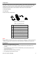
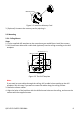
1 Appearance This camera series consists of several different models. Some models are equipped with a zoom lens, in which focus levels must be manually adjusted via a zoom/focus lever. Other models have a motor-driven lens, which allow for zoom and focus adjustment to be completed via web browser or client software. Please refer to the actual device. 1.1 Camera Overview 1.1.1 Overview Camera overview is shown below. 4 1 DC12VI N 5 6 7 3 2 Figure 1-1 Camera Overview Table 1-1 Camera Overview No .
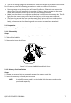
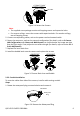
● The wall is strong enough to withstand four times the weight of the camera and mount. For IR cameras, take the following precautions in order to prevent IR reflection: ● Dust or grease on the dome cover will cause IR reflection. Please do not remove the dome cover film until installation is complete. If there is dust or grease on the dome cover, clean the dome cover with a soft cloth and isopropyl alcohol. ● Make sure that there is no reflective surface that is too close to the camera lens.
Memory Card Figure 2-2 Install the Memory Card 3. (Optional) Unmount the memory card by ejecting it. 2.2 Mounting 2.2.1 Ceiling Mount Steps: 1. Fix the supplied drill template to the area where you would like to install the camera. 2. Drill three screw holes and a cable hole (optional) into the ceiling according to the drill template. 43 .3 mm (1 .7" ) 25 mm 50 mm (0.98" ) (1.97" ) 50.3 mm (1.98" ) 58 mm (2.28" ) 29 mm (1.
Back Box Figure 2-4 Secure the Camera Note: The supplied screw package contains self-tapping screws and expansion bolts. ● For cement ceilings, secure the camera with expansion bolts. For wooden ceilings, use self-tapping screws. 5. Connect corresponding cables, such as the power cord and network cable. 6. Power the camera on, and set the network configuration (for details, refer to 3 Camera LAN Configuration and 4 Access via Web Browser) to check whether the image was shot from the right angle.
2. Route the cables through the side outlet towards the conduit. 3. Insert the conduit into the outlet and tighten counterclockwise. Conduit Figure 2-7 Install the Cable Conduit Note: When mounting on a wall, position the side outlet downwards to prevent the collection of water. Downward Figure 2-8 Conduit Outlet Direction 2.3 Image and Focus Adjustment Before you start: Connect the camera to a monitor with the supplied auxiliary video output cable, and power the camera on.
Video Out Interface Figure 2-10 Camera Video-Out Interface 2.3.1 3-Axis Adjustment Steps: 1. View camera output on the monitor. 2. Loosen the tilt adjusting screw to adjust the tilt angle [0° to 70°], hold the black liner to adjust the pan angle [0° to 355°], and hold the lens to rotate the camera [0° to 355°]. Tilt: 0° to 70° Pan: 0° to 355° Rotate: 0° to 355° Figure 2-11 3-Axis Adjustment 2.3.2 Zoom and Focus Adjustment Manual Adjustment: Some camera models in this series have a zoom lens.
5. Tighten the focus lever. Motor-driven Lens: Some camera models in this series are equipped with a motor-driven lens. Adjust the zoom and focus level in the PTZ control panel found in the Web browser or client software. Web Browser Zoom and Focus Adjustment 3 Camera LAN Configuration Note: The use of products with internet access carries inherent security risks. In order to avoid network attacks and information leakage, strengthen your own network protection.
3.2.1 Activation via Web Browser Steps: 1. Power the camera on. Connect the camera to your computer or the switch/router that your computer connects to. 2. Input the IP address into the address bar of the web browser, and press Enter to enter the activation interface. Notes: The camera’s default IP address is 192.168.1.64. The computer and the camera should belong to the same subnet. For cameras that have DHCP enabled by default, use the SADP software to search for the IP address.
Select inactive device. Input and confirm password. Figure 3-4 SADP Interface Note: SADP supports batch camera activations. Refer to the SADP user manual for further details. 3. Create, input, and confirm the password. STRONG PASSWORD RECOMMENDED – We highly recommend creating a strong password of your own choosing (using a minimum of eight characters, including upper case letters, lower case letters, numbers, and special characters) in order to increase the security of your product.
Figure 3-5 Modify the IP Address Note: Hik-Connect can be enabled during activation. Refer to Chapter 5.1 for detailed information. 4. Input the admin password and click Modify to complete IP address modification. SADP supports batch IP address modification. Refer to the SADP user manual for details. 4 Access via Web Browser System Requirement: Operating System: Microsoft Windows XP SP1 and above CPU: 2.
The admin user should configure the device accounts and user/operator permissions properly. Delete the unnecessary accounts and user/operator permissions. Note: The device IP address gets locked if the admin user performs seven failed password attempts (five attempts for the user/operator). 4. Click Login. Figure 4-1 Login Interface 5. Install the plug-in before viewing the live video and managing the camera. Follow the installation prompts to install the plug-in.
2). For the “Modify Network Parameters” page that appears while modifying the IP address, refer to Chapter 3.3. 2. Create or change the verification code. Figure 5-1 Verification Code Setting (SADP) Note: The verification code is required when adding the camera to Hik-Connect. 3. Click and read the “Terms of Service” and “Privacy Policy.” 4. Confirm the settings. 5.2.1 Enable Hik-Connect via a Web Browser Before You Start: Activate the camera before enabling the service. Refer to Chapter 3.2.
Figure 5-2 Platform Access Configuration (Web) 3. Set the Platform Access Mode to Hik-Connect. 4. Check the Enable checkbox. 5. Click and read the “Terms of Service” and “Privacy Policy” in the pop-up window. 6. Create or change the verification code for the camera. Note: A verification code is required when you add the camera to Hik-Connect. 7. Save the settings. 5.3 Add Camera to Hik-Connect Before You Start: You need to enable Hik-Connect on the camera before adding it to your Hik-Connect account.
Note: For detailed information, refer to the Hik-Connect user manual. 5.4 Initialize the Memory Card Note: The microSD memory card is not included with the camera and must be purchased separately. Steps: 1. Check the status of the memory card by tapping on the Storage Status in the Device Settings interface. 2. If the memory card status displays as Uninitialized, tap to initialize it. The status will then change to Normal.
QSG VE ECI-D62Z2 030218NA 20