Network Turret Camera ECI-T22Fx Quick Start Guide
Manual Illustrations and Features Graphics (screen shots, product pictures, etc.) in this document are for illustrative purposes only. Your actual product may differ in appearance. Your product might not support all features discussed in this document. Hikvision USA Inc., 18639 Railroad St., City of Industry, CA 91748, USA • Hikvision Canada, 4848 rue Levy, Saint Laurent, Quebec, Canada, H4R 2P1 Telephone: +1-909-895-0400 • Toll Free in USA: +1-866-200-6690 • E-Mail: sales.usa@hikvision.com • www.hikvision.
CONFORMS THE APPLICABLE LAW. HIKVISION SHALL NOT BE LIABLE IN THE EVENT THAT THIS PRODUCT IS USED WITH ILLEGITIMATE PURPOSES. IN THE EVENT OF ANY CONFLICTS BETWEEN THIS MANUAL AND THE APPLICABLE LAW, THE LATER PREVAILS. Regulatory Information FCC Information Please take attention that changes or modification not expressly approved by the party responsible for compliance could void the user’s authority to operate the equipment.
These instructions are intended to ensure that user can use the product correctly to avoid danger or property loss. The precaution measure is divided into “Warnings” and “Cautions” Warnings: Serious injury or death may occur if any of the warnings are neglected. Cautions: Injury or equipment damage may occur if any of the cautions are neglected. Warnings Follow these safeguards to prevent serious injury or death. Cautions Follow these precautions to prevent potential injury or material damage.
● ● ● ● ● ● To avoid heat accumulation, good ventilation is required for operating environment. Keep the camera away from liquid while in use. While in delivery, the camera shall be packed in its original packing, or packing of the same texture. Regular part replacement: a few parts (e.g. electrolytic capacitor) of the equipment shall be replaced regularly according to their average enduring time.
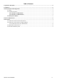
Table of Contents 1 Appearance Description ................................................................................................................................................. 0 2 Installation ...................................................................................................................................................................... 0 3 Network Camera LAN Configuration.......................................................................................................
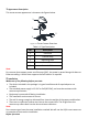
1 Appearance Description This turret camera appearance is shown as the figures below. 1 2 5 4 3 Figure 1-1 Turret Camera Overview Table 1-1 Type Description No. Description 1 Enclosure 2 Camera Body 3 Mounting Base 4 Power Cord 5 Network Cable Note: For cameras that support power over Ethernet (PoE), the power is passed along with data on Ethernet cabling. A switch that supports the PoE function is required.
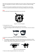
Both wall and ceiling mounting are suitable for the turret camera. Ceiling mounting will be used as an example for this section, and can be used as a reference for wall mounting. Steps: 1. Paste the drill template (supplied) to the desired mounting position on the ceiling. 2. Drill the screw holes and the cable hole in the ceiling according to the drill template. Note: Drill the cable hole if using the ceiling outlet to route the cable. mm 4.2 7 ) 3-Φ (0.1 " Screw Hole m m ) 85 5" Φ 3.3 mm ( 10 ) " Φ1 4.
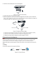
6. Install the camera body back to the mounting base. Figure 2-4 Install the Camera Body 7. Connect the power cord and network cable. 8. Power the camera on, and set the network configuration (for details, refer to 3 Network Camera LAN Configuration and 4 Access via Web Browser) to check whether the image is at an optimum angle. If not, adjust the surveillance angle. Pan: 0° to 360° Rotation: 0° to 360° Tilt: 0° to 75° Figure 2-5 Adjust Surveillance Angle 1).
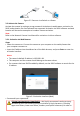
or ork tw Ne le Cab Ne two rk Cab le or Network Camera Computer Figure 3-2 Connect via a Switch or a Router 3.2 Activate the Camera Activate the camera by setting a strong password. Activation via web browser, activation via SADP, and activation via client software are supported. Activation via SADP software and web browser will be used as examples to introduce camera activation. Note: Refer to the Network Camera User Manual for activation via client software. 3.2.
increase the security of your product. We recommend regularly resetting your password on a weekly or monthly basis, especially in high security systems. 4. Confirm the password. 5. Click OK to save the password and enter the live view interface. 3.2.2 Activation via SADP Software SADP software is used for detecting online devices, activating cameras, and resetting passwords. SADP can be obtained from the supplied disk or the official website, and installed by following the prompts.
3.3 Modify the IP Address Purpose: To view and configure the camera via LAN (Local Area Network), you need to connect the network camera in the same subnet as your PC. Use the SADP software or client software to search and change the IP address of the device. IP Address modification via SADP software will be used as an example. In order to modify the IP address via client software, refer to the user manual of the client software. Steps: 1. Run SADP. 2. Select an active device. 3.
4 Access via Web Browser System Requirement: Operating System: Microsoft Windows XP SP1 and above CPU: 2.0 GHz or greater RAM: 1 Gb or greater Display: 1024×768 resolution or higher Web Browser: Internet Explorer 8.0 or higher, Apple Safari 5.0.2 or higher, Mozilla Firefox 5.0 or higher, and Google Chrome 18 or higher Steps: 1. Open the Web browser. 2. In the browser address bar, input the IP address of the network camera, and press the Enter key to enter the login interface.
5 Hik-Connect Purpose: Hik-Connect is a mobile application to view live camera images, receive alarm notifications, etc. 5.1 Enable Hik-Connect for Use with Cameras Purpose: Enable Hik-Connect should on your camera before using the service. You can enable the service either via SADP software or a Web browser. 5.2 Enable Hik-Connect Service via SADP Software Steps: 1. Check the Enable Hik-Connect checkbox: 1). For the “Activate the Device” page that appears during camera activation, refer to Chapter 3.2.2.
5.2.1 Enable Hik-Connect via a Web Browser Before You Start: Activate the camera before enabling the service. Refer to Chapter 3.2. for more information. Steps: 1. Access the camera via the Web browser. Refer to Chapter 4. 2. Enter the platform access configuration interface, as follows: Configuration > Network > Advanced Settings > Platform Access. Figure 5-2 Platform Access Configuration (Web) 3. Set the Platform Access Mode to Hik-Connect. 4. Check the Enable checkbox. 5.
Note: After the camera connects to the network, wait one minute before using the camera with Hik-Connect. 2. Add the camera to the Hik-Connect app: • If Accessing the Camera through an NVR: Tap “+” on the upper-right corner and scan the QR code that appears in the NVR interface. • If Accessing the Camera through a Web Browser: Tap the camera’s serial number. icon and type in the 3. Input your camera’s verification code.