Network Speed Dome Camera EPI-4215-DE3 Quick Start Guide
Manual Illustrations and Features Graphics (screen shots, product pictures, etc.) in this document are for illustrative purposes only. Your actual product may differ in appearance. Your product might not support all features discussed in this document. Hikvision USA Inc., 18639 Railroad St., City of Industry, CA 91748, USA • Hikvision Canada, 4848 rue Levy, Saint Laurent, Quebec, Canada, H4R 2P1 Telephone: +1-909-895-0400 • Toll Free in USA: +1-866-200-6690 • E-Mail: sales.usa@hikvision.com • www.hikvision.
REGARDING TO THE PRODUCT WITH INTERNET ACCESS, THE USE OF PRODUCT SHALL BE WHOLLY AT YOUR OWN RISKS. HIKVISION SHALL NOT TAKE ANY RESPONSIBILITES FOR ABNORMAL OPERATION, PRIVACY LEAKAGE OR OTHER DAMAGES RESULTING FROM CYBER ATTACK, HACKER ATTACK, VIRUS INSPECTION, OR OTHER INTERNET SECURITY RISKS; HOWEVER, HIKVISION WILL PROVIDE TIMELY TECHNICAL SUPPORT IF REQUIRED. SURVEILLANCE LAWS VARY BY JURISDICTION.
2006/66/EC (Battery Directive): This product contains a battery that cannot be disposed of as unsorted municipal waste in the European Union. See the product documentation for specific battery information. The battery is marked with this symbol, which may include lettering to indicate cadmium (Cd), lead (Pb), or mercury (Hg). For proper recycling, return the battery to your supplier or to a designated collection point. For more information see: www.recyclethis.info.
If smoke, odor or noise rise from the device, turn off the power at once and unplug the power cable, and then contact the service center. If the product does not work properly, contact your dealer or the nearest service center. Never attempt to disassemble the speed dome yourself. (We shall not assume any responsibility for problems caused by unauthorized repair or maintenance.
Table of Contents 1 Overview ...................................................................................................... 7 1.1 Speed Dome Overview .............................................................................................7 1.1.1 Overview of EPI-4215-DE3 Speed Dome ............................................................7 1.2 Cable Interfaces ........................................................................................................7 2 Installation ............
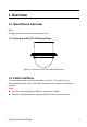
1 Overview 1.1 Speed Dome Overview Note: The figures below are for reference purposes only. 1.1.1 Overview of EPI-4215-DE3 Speed Dome Figure 1-1 Overview of EPI-4215-DE3 Speed Dome 1.2 Cable Interfaces The speed dome cable interfaces are shown in Figure 1-2. The cables can be differentiated by color. Refer to the labels attached to the cables for identification purposes. Notes: The cables vary depending on different speed dome models.
Figure 1-2 Cable Interfaces 2 Installation Before You Start: Check the contents and make sure that the device in the package is in good condition, and that all required parts are included. Notes: Do not touch the bubble. This might cause image blur. Do not power the speed dome on until installation is finished. To ensure the safety of personnel and equipment, all the installation steps should be performed with the power off.
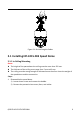
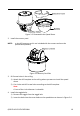
Figure 2-1 Do Not Drag the Cables 2.1 Installing EPI-4215-DE3 Speed Dome 2.1.1 In-Ceiling Mounting Notes: The height of the space above the ceiling must be more than 250 mm. The thickness of the ceiling must range from 5 mm to 40 mm. The ceiling must be strong enough to withstand more than four times the weight of the speed dome and the accessories. Steps: 1. Disassemble the speed dome. 1) Loosen three screws and remove the bubble. 2) Remove the protective lens cover, foam, and sticker.
Figure 2-2 Disassemble the Speed Dome 2. Install the memory card. NOTE: a microSD memory card is not included with the camera and must be purchased separately. Figure 2-3 Memory Card Slot 3. Drill screw holes in the ceiling. 1) Attach the drill template to the ceiling where you want to install the speed dome. 2) Cut a hole and drill screw holes according to the drill template. Note: ±2 mm of the circle diameter is tolerable. 4. Install the toggle bolts. 1) Remove the toggle from the toggle bolt.
Figure 2-4 Toggle Bolt Holes 3) Rotate the bolts through the screw holes. 4) Install the toggles back as shown in Figure 2-5. Figure 2-5 Install the Toggle Bolts 5. Install the speed dome to the ceiling. 1) Align the toggle bolts with the screw holes on the ceiling. 2) Push the speed dome to the mounting hole on the ceiling. 3) Rotate the bolts again. The toggle will automatically rotate down to secure the speed dome to the ceiling.
4) Secure the bubble to the speed dome with three screws as shown in Figure 2-7. Figure 2-7 Secure the Bubble 6. Route the cables through the ceiling. 7. Remove the protective film on the bubble after the installation is finished. 3 Speed Dome LAN Configuration Notes: The use of products with internet access carries inherent security risks. In order to avoid network attacks and information leakage, strengthen your own network protection.
Figure 3-2 Wiring over LAN 3.2 Activating the Speed Dome Purpose: You are first required to activate the speed dome by setting a strong password. Activation via Web browser, SADP, and client software are supported. We will consider activation via SADP and Web browser as examples to introduce speed dome activation. 3.2.1 Activation via Web Browser Steps: 1. Power on the speed dome. Connect the speed dome to your computer or the switch/router that your computer connects to. 2.
3. Create and input a password. STRONG PASSWORD RECOMMENDED – We highly recommend that you create a strong password of your own choosing (using a minimum of eight characters, including at least three of the following categories: upper case letters, lower case letters, numbers, and special characters) in order to increase the security of your product. We also recommend that you reset your password regularly.
STRONG PASSWORD RECOMMENDED – We highly recommend that you create a strong password of your own choosing (using a minimum of eight characters, including at least three of the following categories: upper case letters, lower case letters, numbers, and special characters) in order to increase the security of your product. We also recommend that you reset your password regularly. Especially in a high security system, resetting the password monthly or weekly can better protect your product.
Figure 3-5 Modify the IP Address Note: You can enable the Hik-Connect service for the device during activation. Refer to Section 1.1 Error! Reference source not found.. 4. Input the admin password and click Modify to activate your IP address modification. Batch IP address modification is supported by SADP. Refer to the SADP user manual for details.
Steps: 1. Open the Web browser. 2. In the browser address bar, input the IP address of the network speed dome, and enter the login interface. Note: The default IP address is 192.168.1.64. You are recommended to change the IP address to the same subnet as your computer. 3. Input the user name and password. The admin user should configure the device accounts and user/operator permissions properly. Delete unnecessary accounts and user/operator permissions.
Note: For configuration instructions, refer to the network speed dome user manual. 1 Hik-Connect Purpose: Hik-Connect is a mobile application to view live camera images, receive alarm notifications, etc. 1.1 Enable Hik-Connect for Use with Cameras Purpose: Enable Hik-Connect should on your camera before using the service. You can enable the service either via SADP software or a Web browser. 1.2 Enable Hik-Connect Service via SADP Software Steps: 1. Check the Enable Hik-Connect checkbox: 1).
1.2.1 Enable Hik-Connect via a Web Browser Before You Start: Activate the camera before enabling the service. Refer to Chapter 3.2. for more information. Steps: 1. Access the camera via the Web browser. Refer to Chapter 4. 2. Enter the platform access configuration interface, as follows: Configuration > Network > Advanced Settings > Platform Access. Figure 4-4 Platform Access Configuration (Web) 3. Set the Platform Access Mode to Hik-Connect. 4. Check the Enable checkbox. 5.
Figure 4-5 Connect a Router Note: After the camera connects to the network, wait one minute before using the camera with Hik-Connect. 2. Add the camera to the Hik-Connect app: • If Accessing the Camera through an NVR: Tap “+” on the upper-right corner and scan the QR code that appears in the NVR interface. • If Accessing the Camera through a Web Browser: Tap the camera’s serial number. icon and type in the 3. Input your camera’s verification code.
QSG EPI-4215-DE3 030518NA 21