Network Camera User Manual
Network Camera User Manual Legal Information © 2020 Hangzhou Hikvision Digital Technology Co., Ltd. All rights reserved. About this Manual The Manual includes instructions for using and managing the Product. Pictures, charts, images and all other information hereinafter are for description and explanation only. The information contained in the Manual is subject to change, without notice, due to firmware updates or other reasons.
Network Camera User Manual PUBLICITY, INTELLECTUAL PROPERTY RIGHTS, OR DATA PROTECTION AND OTHER PRIVACY RIGHTS. YOU SHALL NOT USE THIS PRODUCT FOR ANY PROHIBITED END-USES, INCLUDING THE DEVELOPMENT OR PRODUCTION OF WEAPONS OF MASS DESTRUCTION, THE DEVELOPMENT OR PRODUCTION OF CHEMICAL OR BIOLOGICAL WEAPONS, ANY ACTIVITIES IN THE CONTEXT RELATED TO ANY NUCLEAR EXPLOSIVE OR UNSAFE NUCLEAR FUEL-CYCLE, OR IN SUPPORT OF HUMAN RIGHTS ABUSES.
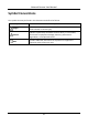
Network Camera User Manual Symbol Conventions The symbols that may be found in this document are defined as follows. Symbol Description Danger Indicates a hazardous situation which, if not avoided, will or could result in death or serious injury. Caution Indicates a potentially hazardous situation which, if not avoided, could result in equipment damage, data loss, performance degradation, or unexpected results.
Network Camera User Manual Safety Instruction These instructions are intended to ensure that user can use the product correctly to avoid danger or property loss. Laws and Regulations ● The device should be used in compliance with local laws, electrical safety regulations, and fire prevention regulations. Transportation ● Keep the device in original or similar packaging while transporting it.
Network Camera User Manual Emergency ● If smoke, odor, or noise arises from the device, immediately turn off the power, unplug the power cable, and contact the service center. Time Synchronization ● Set up camera time manually for the first time access if the local time is not synchronized with that of the network. Visit the camera via Web browse/client software and go to time settings interface.
Network Camera User Manual Contents Chapter 1 System Requirement .................................................................................................. 1 Chapter 2 Device Activation and Accessing ................................................................................. 2 2.1 Activate the Device via SADP ................................................................................................ 2 2.2 Activate the Device via Browser ...................................................
Network Camera User Manual 4.1.3 Resolution ................................................................................................................. 13 4.1.4 Bitrate Type and Max. Bitrate ................................................................................. 13 4.1.5 Video Quality ............................................................................................................ 13 4.1.6 Frame Rate .................................................................................
Network Camera User Manual 5.1.3 Set NAS ..................................................................................................................... 28 5.1.4 eMMC Protection ..................................................................................................... 29 5.1.5 Set Cloud Storage ..................................................................................................... 29 5.2 Video Recording ..........................................................................
Network Camera User Manual 6.2.10 Set Unattended Baggage Detection ...................................................................... 47 6.2.11 Set Object Removal Detection ............................................................................... 48 6.2.12 Draw Area ............................................................................................................... 49 6.2.13 Set Size Filter .................................................................................................
Network Camera User Manual Chapter 8 Arming Schedule and Alarm Linkage ......................................................................... 68 8.1 Set Arming Schedule ........................................................................................................... 68 8.2 Linkage Method Settings..................................................................................................... 68 8.2.1 Trigger Alarm Output ......................................................................
Network Camera User Manual 9.14.2 Set IP Address Filter ............................................................................................... 79 9.14.3 Set HTTPS ................................................................................................................ 79 9.14.4 Set QoS.................................................................................................................... 80 9.14.5 Set IEEE 802.1X ...................................................................
Network Camera User Manual 10.3.1 Set Multi-Target-Type Detection Rule................................................................... 93 10.3.2 Overlay and Capture .............................................................................................. 93 10.3.3 Multi-Target-Type Detection Algorithm Parameters............................................ 94 10.3.4 Set Shield Region .................................................................................................... 95 10.
Network Camera User Manual Chapter 1 System Requirement Your computer should meet the requirements for proper visiting and operating the product. Operating System Microsoft Windows XP SP1 and above version CPU 2.0 GHz or higher RAM 1G or higher Display 1024×768 resolution or higher Web Browser Internet Explorer 8.0 and above version, Mozilla Firefox 30.
Network Camera User Manual Chapter 2 Device Activation and Accessing To protect the security and privacy of the user account and data, you should set a login password to activate the device when access the device via network. Note Refer to the user manual of the software client for the detailed information about the client software activation. 2.1 Activate the Device via SADP Search and activate the online devices via SADP software. Before You Start Access www.hikvision.
Network Camera User Manual Note The default IP address of the device is 192.168.1.64. You can set the IP address of the PC from 192.168.1.2 to 192.168.1.253 (except 192.168.1.64). For example, you can set the IP address of the PC to 192.168.1.100. 3. Input 192.168.1.64 in the browser. 4. Set device activation password.
Network Camera User Manual Operating System Web Browser Operation Plug-in installation is not required. Mac OS ● Google Chrome 57+ ● Mozilla Firefox 52+ ● Mac Safari 16+ Go to Configuration → Network → Advanced Settings → Network Service to enable WebSocket or Websockets for normal view. Display and operation of certain functions are restricted. For example, Playback and Picture are not available. For detailed restricted function, refer to the actual device.
Network Camera User Manual 2.3.3 Illegal Login Lock It helps to improve the security when accessing the device via Internet. The admin user can set the login attempts with the wrong password. When your login attempts with the wrong password reach the set times, the device is locked. Go to Configuration → System → Security → Security Service, and enable Enable Illegal Login Lock, and set the illegal login attempts.
Network Camera User Manual Chapter 3 Live View It introduces the live view parameters, function icons and transmission parameters settings. 3.1 Live View Parameters The supported functions vary depending on the model. 3.1.1 Enable and Disable Live View This function is used to quickly enable or disable live view of all channels. ● Click to start live view of all channels. ● Click to stop live view of all channels. 3.1.2 Adjust Aspect Ratio Steps 1. Click Live View. 2. Click to select the aspect ratio.
Network Camera User Manual QuickTime, VLC or MJPEG. 3.1.5 Window Division ● ● ● ● refers to 1 × 1 window division. refers to 2 × 2 window division. refers to 3 × 3 window division. refers to 4 × 4 window division. 3.1.6 Light Click to turn on or turn off the illuminator. 3.1.7 Count Pixel It helps to get the height and width pixel of the selected region in the live view image. Steps 1. Click to enable the function. 2. Drag the mouse on the image to select a desired rectangle area.
Network Camera User Manual 3.1.10 Lens Initialization Lens initialization is used on the device equipped with motorized lens. The function can reset lens when long time zoom or focus results in blurred image. This function varies according to different models. Manual Lens Initialization Click to operate lens initialization. Auto Lens Initialization Go to Configuration → System → Maintenance → Lens Correction to enable this function.
Network Camera User Manual PTZ Speed Slide to adjust the speed of the pan/tilt movement. Iris ● When the image is too dark, click to enlarge the iris. ● When the image is too bright, click to stop down the iris. 3.1.13 Conduct 3D Positioning 3D positioning is to relocate the selected area to the image center. Steps 1. Click to enable the function. 2. Select a target area in live image. – Left click on a point on live image: the point is relocated to the center of the live image.
Network Camera User Manual Note For detailed information about multicast, refer to Multicast. HTTP HTTP is suitable for the situation that the third-party needs to get the stream from the device. Play Performance Shortest Delay The device takes the real-time video image as the priority over the video fluency. Balanced The device ensures both the real-time video image and the fluency. Fluent The device takes the video fluency as the priority over teal-time.
Network Camera User Manual you enable smooth streaming function. In this mode, the frame rate will be adjusted to the maximum value automatically. Resolution Priority The resolution stays the same as the set value on Video page, and the bitrate will be adjusted automatically. Go to Configuration → Video/Audio → Video, set the Max. Bitrate before you enable smooth streaming function. In this mode, the framerate will be adjusted to the maximum value automatically.
Network Camera User Manual Chapter 4 Video and Audio This part introduces the configuration of video and audio related parameters. 4.1 Video Settings This part introduces the settings of video parameters, such as, stream type, video encoding, and resolution. Go to setting page: Configuration → Video/Audio → Video. 4.1.1 Stream Type For device supports more than one stream, you can specify parameters for each stream type. Main Stream The stream stands for the best stream performance the device supports.
Network Camera User Manual Note Up to 32 letters and symbols (except &, <, >, ', or ") are allowed for the stream name. 3. Customize the stream parameters (resolution, frame rate, max. bitrate, video encoding). 4. Optional: Add stream description as needed. 5. Optional: If a custom stream is not needed, click to delete it. 6. Click Save. 4.1.2 Video Type Select the content (video and audio) that should be contained in the stream. Video Only video content is contained in the stream.
Network Camera User Manual measured by frames per second (fps). A higher frame rate is advantageous when there is movement in the video stream, as it maintains image quality throughout. Note that higher frame rate requires higher bandwidth and larger storage space. 4.1.7 Video Encoding It stands for the compression standard the device adopts for video encoding. Note Available compression standards vary according to device models. H.264 H.
Network Camera User Manual is less satisfactory. Max. average bitrate should not be higher than max. bitrate. Note When H.265+ is enabled, Video Quality, I Frame Interval, Profile and SVC are not configurable. I-Frame Interval I-frame interval defines the number of frames between 2 I-frames. In H.264 and H.265, an I-frame, or intra frame, is a self-contained frame that can be independently decoded without any reference to other images. An I-frame consumes more bits than other frames.
Network Camera User Manual of the stream will be, though, the video quality may not be so satisfactory. The lower value of the smoothing is, the higher quality of the stream will be, though it may appear not fluent. 4.2 ROI ROI (Region of Interest) encoding helps to discriminate the ROI and background information in video compression. The technology assigns more encoding resource to the region of interest, thus to increase the quality of the ROI whereas the background information is less focused. 4.2.
Network Camera User Manual image of the face is clearer than that of the surrounding area. Steps 1. Go to the ROI setting page: Configuration → Video/Audio → ROI. 2. Check Enable Face Tracking. 3. Select ROI Level in Dynamic Region. Note ROI level means the image quality enhancing level. The larger the value is, the better the image quality would be. 4. Click Save. 4.2.3 Set Target Tracking ROI The moving target is clearer than other areas in live image or recordings after enabling the function.
Network Camera User Manual 4.3 Display Info. on Stream The information of the objects (e.g. human, vehicle, etc.) is marked in the video stream. You can set rules on the connected rear-end device or client software to detect the events including line crossing, intrusion, etc. Steps 1. Go to the setting page: Configuration → Video/Audio → Display Info. on Stream. 2. Check Enable Dual-VCA. 3. Click Save. 4.
Network Camera User Manual modes. 4.4.4 Environmental Noise Filter Set it as OFF or ON. When the function is enabled, the noise in the environment can be filtered to some extent. 4.5 Two-way Audio It is used to realize the two-way audio function between the monitoring center and the target in the monitoring screen. Before You Start ● Make sure the audio input device (pick-up or microphone) and audio output device (speaker) connected to the device is working properly.
Network Camera User Manual displayed. Exposure Settings Exposure is controlled by the combination of iris, shutter, and photo sensibility. You can adjust image effect by setting exposure parameters. In manual mode, you need to set Exposure Time, Gain and Slow Shutter. Focus It offers options to adjust the focus mode and the minimum focus distance. Focus Mode Auto The device focuses automatically as the scene changes.
Network Camera User Manual Two trigger modes are available: Day and Night. For example, if the trigger mode is Night, the image turns black and white when the device receives alarm input signal. Note Day/Night Switch function varies according to models. Grey Scale You can choose the range of the Grey Scale as [0-255] or [16-235]. Rotate When enabled, the live view will rotate 90 ° counterclockwise. For example, 1280 × 720 is rotated to 720 × 1280.
Network Camera User Manual HLC When the bright area of the image is over-exposed and the dark area is under-exposed, the HLC (High Light Compression) function can be enabled to weaken the bright area and brighten the dark area, so as to achieve the light balance of the overall picture. White Balance White balance is the white rendition function of the camera. It is used to adjust the color temperature according to the environment.
Network Camera User Manual 4.6.2 Image Parameters Switch The device automatically switches image parameters in set time periods. Go to image parameters switch setting page: Configuration → Image → Image Parameters Switch, and set parameters as needed. Set Scheduled-switch Switch the image to the linked scene mode automatically in certain time periods. Steps 1. Check Scheduled-switch. 2. Select and configure the corresponding time period and linked scene mode.
Network Camera User Manual Displayed Information Set camera name, date, week, and their related display format. Text Overlay Set customized overlay text on image. OSD Parameters Set OSD parameters, such as Display Mode, OSD Size, Font Color, and Alignment. 4.8 Set Privacy Mask The function blocks certain areas in the live view to protect privacy. No matter how the device moves, the blocked scene will never be seen. Steps 1. Go to privacy mask setting page: Configuration → Image → Privacy Mask. 2.
Network Camera User Manual The picture with a red rectangle will appear in live view after successfully uploading. 3. Check Enable Picture Overlay. 4. Drag the picture to adjust its position. 5. Click Save. 4.10 Set Target Cropping You can crop the image, transmit and save only the images of the target area to save transmission bandwidth and storage. Steps 1. Go to Configuration → Video/Audio → Target Cropping. 2. Check Enable Target Cropping and set Third Stream as the Stream Type.
Network Camera User Manual Chapter 5 Video Recording and Picture Capture This part introduces the operations of capturing video clips and snapshots, playback, and downloading captured files. 5.1 Storage Settings This part introduces the configuration of several common storage paths. 5.1.1 Set Memory Card If you choose to store the files to memory card, make sure you insert and format the memory card in advance. Before You Start Insert the memory card to the camera.
Network Camera User Manual influenced by factors such as its capacity and the bitrate. You need to change the memory card if the remaining lifespan is not enough. Health Status It shows the condition of your memory card. There are three status descriptions, good, bad, and damaged. You will receive a notification if the health status is anything other than good when the Arming Schedule and Linkage Method are set. Note It is recommended that you change the memory card when the health status is not “good”. 3.
Network Camera User Manual Steps 1. Go to Configuration → Network → Advanced Settings → FTP. 2. Configure FTP settings. FTP Protocol FTP and SFTP are selectable. The files uploading is encrypted by using SFTP protocol. Server Address and Port The FTP server address and corresponding port. User Name and Password The FTP user should have the permission to upload pictures. If the FTP server supports picture uploading by anonymous users, you can check Anonymous to hide your device information during uploading.
Network Camera User Manual Steps 1. Go to NAS setting page: Configuration → Storage → Storage Management → Net HDD. 2. Click HDD No.. Enter the server address and file path for the disk. Server Address The IP address of the network disk. File Path The saving path of network disk files. Mounting Type Select file system protocol according to the operation system. Enter user name and password of the net HDD to guarantee the security if SMB/CIFS is selected. 3.
Network Camera User Manual ID sure storage pool ID and the storage region ID are the same. 4. Click Test to test the configured settings. 5. Click Save. 5.2 Video Recording This part introduces the operations of manual and scheduled recording, playback, and downloading recorded files. 5.2.1 Record Automatically This function can record video automatically during configured time periods. Before You Start Select Trigger Recording in event settings for each record type except Continuous.
Network Camera User Manual Event The video is recorded when configured event is detected. 4. Set schedule for the selected record type. Refer to Set Arming Schedule for the setting operation. 5. Click Advanced to set the advanced settings. Overwrite Enable Overwrite to overwrite the video records when the storage space is full. Otherwise the camera cannot record new videos. Pre-record The time period you set to record before the scheduled time.
Network Camera User Manual 2. Check Enable and set the level. The higher the level is, the larger the frame rate and bitrate are, and the shorter the recommended storage time is. 3. Set the storage time. The device automatically calculates the bitrate and offers the recommended storage time according to the memory card space and level. You are recommended to set the storage time to the device recommended time. Note ● If the lite storage is enabled, unformatted memory card will be formatted automatically.
Network Camera User Manual path. You can view and download the snapshots. 5.3.1 Capture Automatically This function can capture pictures automatically during configured time periods. Before You Start If event-triggered capture is required, you should configure related linkage methods in event settings. Refer to Event and Alarm for event settings. Steps 1. Go to Configuration → Storage → Schedule Settings → Capture → Capture Parameters. 2. Set the capture type.
Network Camera User Manual The matched pictures showed in the file list. 3. Select the pictures then click Download to download them. Note Go to Configuration → Local, click Save snapshots when playback to change the saving path of pictures.
Network Camera User Manual Chapter 6 Event and Alarm This part introduces the configuration of events. The device takes certain response to triggered alarm. 6.1 Basic Event 6.1.1 Set Motion Detection It helps to detect the moving objects in the detection region and trigger the linkage actions. Steps 1. Go to Configuration → Event → Basic Event → Motion Detection. 2. Check Enable Motion Detection. 3. Optional: Highlight to display the moving object in the image in green.
Network Camera User Manual Sensitivity The higher the value of sensitivity is, the more sensitive the motion detection is. If the sensitivity is set to 0, motion detection and dynamic analysis do not take effect. Proportion It refers to the proportion that a moving object occupies in the drawn area. When the size of the object exceeds the set proportion, motion detection is triggered. 3. Select an Area and click Draw Area.
Network Camera User Manual Figure 6-2 Set Rules Stop Drawing Stop drawing one area. Clear All Clear all the areas. 4. Optional: You can set the parameters of multiple areas by repeating the above steps. 6.1.2 Set Video Tampering Alarm When the configured area is covered and cannot be monitored normally, the alarm is triggered and the device takes certain alarm response actions. Steps 1. Go to Configuration → Event → Basic Event → Video Tampering. 2. Check Enable. 3. Set the Sensitivity.
Network Camera User Manual Figure 6-3 Set Video Tampering Area 5. Refer to Set Arming Schedule for setting scheduled time. Refer to Linkage Method Settings for setting linkage method. 6. Click Save. 6.1.3 Set PIR Alarm A PIR (Passive Infrared) alarm is triggered when an intruder moves within the detector's field of view. The heat energy dissipated by a person, or any other warm blooded creature such as dogs, cats, etc., can be detected. Steps Note Only certain models support PIR alarm. 1.
Network Camera User Manual 6.1.4 Set Exception Alarm Exception such as network disconnection can trigger the device to take corresponding action. Steps 1. Go to Configuration → Event → Basic Event → Exception. 2. Select Exception Type. HDD Full The HDD storage is full. HDD Error Error occurs in HDD. Network Disconnected The device is offline. IP Address Conflicted The IP address of current device is same as that of other device in the network.
Network Camera User Manual 3. Set the corresponding parameters. Alarm Detection Interval The time interval to detect the exception. Sensitivity The higher the value is, the more easily the exception will be detected, and the higher possibility of misinformation would be. Alarm Delay Times The device uploads the alarm when the alarm reaches the set number of times. 4. Check Enable, and the selected diagnosis type will be detected. 5. Set arming schedule. See Set Arming Schedule. 6. Set linkage method.
Network Camera User Manual 6.2.1 Detect Audio Exception Audio exception detection function detects the abnormal sound in the surveillance scene, such as the sudden increase/decrease of the sound intensity, and some certain actions can be taken as response. Steps 1. Go to Configuration → Event → Smart Event → Audio Exception Detection. 2. Select one or several audio exception detection types. Audio Loss Detection Detect sudden loss of audio track.
Network Camera User Manual 3. Set Sensitivity. The higher the value is, the more easily the defocus image can trigger the alarm. You can adjust the value according to the actual environment. 4. For the linkage method settings, refer to Linkage Method Settings. 5. Click Save. Note The function is only supported by certain models. The actual display varies with models. 6.2.3 Detect Scene Change Scene change detection function detects the change of surveillance scene.
Network Camera User Manual 6.2.5 Set Video Loss This function can detect the video signal loss in time and trigger the linkage action. Steps 1. Go to Configuration → Event → Basic Event → Video Loss. 2. Check Enable. 3. Refer to Set Arming Schedule for setting scheduled time. Refer to Linkage Method Settings for setting linkage method. 4. Click Save. 6.2.6 Set Intrusion Detection It is used to detect objects entering and loitering in a pre-defined virtual region.
Network Camera User Manual Figure 6-4 Set Rule 5. Optional: You can set the parameters of multiple areas by repeating the above steps. 6. For the arming schedule settings, refer to Set Arming Schedule. For the linkage method settings, refer to Linkage Method Settings. 7. Click Save. 6.2.7 Set Line Crossing Detection It is used to detect objects crossing a pre-defined virtual line. If it occurs, the device can take linkage actions. Steps 1.
Network Camera User Manual sensitivity is, the more easily the alarm can be triggered. Object You can specify the object type to be detected and the device only detects the selected type of object. Figure 6-5 Set Rule 6. Optional: You can set the parameters of multiple areas by repeating the above steps. 7. For the arming schedule settings, refer to Set Arming Schedule. For the linkage method settings, refer to Linkage Method Settings. 8. Click Save. 6.2.
Network Camera User Manual Figure 6-6 Set Rule 5. Optional: You can set the parameters of multiple areas by repeating the above steps. 6. For the arming schedule settings, refer to Set Arming Schedule. For the linkage method settings, refer to Linkage Method Settings. 7. Click Save. 6.2.9 Set Region Exiting Detection It is used to detect objects exiting from a pre-defined virtual region. If it occurs, the device can take linkage actions. Steps 1.
Network Camera User Manual Figure 6-7 Set Rule 5. Optional: You can set the parameters of multiple areas by repeating the above steps. 6. For the arming schedule settings, refer to Set Arming Schedule. For the linkage method settings, refer to Linkage Method Settings. 7. Click Save. 6.2.10 Set Unattended Baggage Detection It is used to detect the objects left over in the pre-defined region. Linkage methods can be triggered after the object is left and stays in the region for a set time period. Steps 1.
Network Camera User Manual Figure 6-8 Set Rule 5. Optional: You can set the parameters of multiple areas by repeating the above steps. 6. For the arming schedule settings, refer to Set Arming Schedule. For the linkage method settings, refer to Linkage Method Settings. 7. Click Save. 6.2.11 Set Object Removal Detection It detects whether the objects are removed from the pre-defined detection region, such as the exhibits on display.
Network Camera User Manual Figure 6-9 Set Rule 5. Optional: Repeat the above steps to set more regions. 6. For the arming schedule settings, see Set Arming Schedule. For the linkage method settings, see Linkage Method Settings. 7. Click Save. Note The function is only supported by certain models. The actual display varies with the models. 6.2.12 Draw Area This section introduces the configuration of area. Steps 1. Click Draw Area. 2.
Network Camera User Manual value and maximum value is detected and triggers alarm. Steps 1. Click Max. Size, and drag the mouse in the live view to draw the maximum target size. 2. Click Min. Size, and drag the mouse in the live view to draw the minimum target size. 3. Click Save.
Network Camera User Manual Chapter 7 Network Settings 7.1 TCP/IP TCP/IP settings must be properly configured before you operate the device over network. IPv4 and IPv6 are both supported. Both versions can be configured simultaneously without conflicting to each other. Go to Configuration → Basic Configuration → Network → TCP/IP for parameter settings. NIC Type Select a NIC (Network Interface Card) type according to your network condition. IPv4 Two IPv4 modes are available.
Network Camera User Manual Input IPv6 Address, IPv6 Subnet, IPv6 Default Gateway. Consult the network administrator for required information. MTU It stands for maximum transmission unit. It is the size of the largest protocol data unit that can be communicated in a single network layer transaction. The valid value range of MTU is 1280 to 1500. DNS It stands for domain name server. It is required if you need to visit the device with domain name. And it is also required for some applications (e.g.
Network Camera User Manual 7.2 SNMP You can set the SNMP network management protocol to get the alarm event and exception messages in network transmission. Before You Start Before setting the SNMP, you should download the SNMP software and manage to receive the device information via SNMP port. Steps 1. Go to the settings page: Configuration → Network → Advanced Settings → SNMP. 2. Check Enable SNMPv1, Enable SNMP v2c or Enable SNMPv3.
Network Camera User Manual 7.4 Port Mapping By setting port mapping, you can access devices through the specified port. Before You Start When the ports in the device are the same as those of other devices in the network, refer to Port to modify the device ports. Steps 1. Go to Configuration → Network → Basic Settings → NAT. 2. Select the port mapping mode. Auto Port Mapping Refer to Set Auto Port Mapping for detailed information.
Network Camera User Manual 7.4.3 Set Port Mapping on Router The following settings are for a certain router. The settings vary depending on different models of routers. Steps 1. Select the WAN Connection Type. 2. Set the IP Address, Subnet Mask and other network parameters of the router. 3. Go to Forwarding → Virtual Severs, and input the Port Number and IP Address. 4. Click Save.
Network Camera User Manual 7.5 Port The device port can be modified when the device cannot access the network due to port conflicts. Caution Do not modify the default port parameters at will, otherwise the device may be inaccessible. Go to Configuration → Network → Basic Settings → Port for port settings. HTTP Port It refers to the port through which the browser accesses the device. For example, when the HTTP Port is modified to 81, you need to enter http://192.168.1.64:81 in the browser for login.
Network Camera User Manual 7.6 Access to Device via Domain Name You can use the Dynamic DNS (DDNS) for network access. The dynamic IP address of the device can be mapped to a domain name resolution server to realize the network access via domain name. Before You Start Registration on the DDNS server is required before configuring the DDNS settings of the device. Steps 1. Refer to TCP/IP to set DNS parameters. 2. Go to the DDNS settings page: Configuration → Network → Basic Settings → DDNS. 3.
Network Camera User Manual Password Password for dial-up network access. Confirm Input your dial-up password again. 4. Click Save. 5. Access the device. By Browsers Enter the WAN dynamic IP address in the browser address bar to access the device. By Client Software Add the WAN dynamic IP address to the client software. Refer to the client manual for details. Note The obtained IP address is dynamically assigned via PPPoE, so the IP address always changes after rebooting the camera.
Network Camera User Manual Click Refresh Refresh the dial status. Click Disconnect Disconnect the 3G/4G wireless network. When the Dial Status turns to Connected, it means a successful dial. 7. Access the device via the IP Address of the computer in the network. – Input the IP address in the browser to access the device. – Add the device in client application. Select IP/Domain, and input IP address and other parameters to access the device. 7.8.
Network Camera User Manual 7.9.1 Connect Wi-Fi Manually Before You Start Refer to the user manual of wireless router or AP to set SSID, key, and other parameters. Steps 1. Go to TCP/IP settings page: Configuration → Network → Basic Configuration → TCP/IP. 2. Select Wlan to set the parameters. Refer to TCP/IP for detailed configuration. Note For stable use of Wi-Fi, it is not recommended to use DHCP. 3. Go to Wi-Fi settings page: Configuration → Network → Advanced Configuration → Wi-Fi. 4.
Network Camera User Manual Note For stable use of Wi-Fi, it is not recommended to use DHCP. 3. Go to Wi-Fi settings page: Configuration → Network → Advanced Configuration → Wi-Fi. 4. Set Wi-Fi parameters. 1) Check Enable WPS. 2) Select PBC connection. 3) Check on the Wi-Fi router to see if there is a WPS button. If yes push the button and you can see the indicator near the button start flashing, which means the WPS function of the router is enabled.
Network Camera User Manual – Input the IP address in the browser to access the device. – Add the device in client application. Select IP/Domain, and input IP address and other parameters to access the device. Use PIN on Router The device can automatically connect the network by setting the PIN code of wireless router or AP in device via WPS or QSS protocols. Before You Start Get the PIN code and SSID of the router or AP. Steps 1.
Network Camera User Manual WebSocket & WebSockets WebSocket or WebSockets protocol should be enabled if you use Google Chrome 57 and its above version or Mozilla Firefox 52 and its above version to visit the device. Otherwise, live view, image capture, and digital zoom function cannot be used. If the device uses HTTP, enable WebSocket. If the device uses HTTPS, enable WebSockets and select the server certificate.
Network Camera User Manual transmission. Steps 1. Go to Configuration → Network → Advanced Settings → Alarm Server. 2. Enter Destination IP or Host Name, URL, and Port. 3. Select Protocol. Note HTTP, HTTPS, and ISUP are selectable. It is recommended to use HTTPS, as it encrypts the data transmission during communication. 4. Click Test to check if the IP or host is available. 5. Click Save. 7.13 Access Camera via Hik-Connect Hik-Connect is an application for mobile devices.
Network Camera User Manual 4. In the app, tap "+" on the upper-right corner and then scan the QR code of the camera to add the camera. You can find the QR code on the camera or on the cover of the Quick Start Guide of the camera in the package. 5. Follow the prompts to set the network connection and add the camera to your Hik-Connect account. For detailed information, refer to the user manual of the Hik-Connect app. 7.13.
Network Camera User Manual Note The verification code is required when you add the camera to Hik-Connect service. 5. Click and read "Terms of Service" and "Privacy Policy". 6. Confirm the settings. 7.13.2 Set Up Hik-Connect Steps 1. Get and install Hik-Connect application by the following ways. Visit https://appstore.hikvision.com to download the application according to your mobile phone system.Visit the official site of our company. Then go to Support → Tools → Hikvision App Store.
Network Camera User Manual Note If the QR code is missing or too blur to be recognized, you can also add the camera by inputting the camera's serial number. 5. Input the verification code of your camera. Note ● The required verification code is the code you create or change when you enable Hik-Connect service on the camera. ● If you forget the verification code, you can check the current verification code on Platform Access configuration page via web browser. 6.
Network Camera User Manual Chapter 8 Arming Schedule and Alarm Linkage Arming schedule is a customized time period in which the device performs certain tasks. Alarm linkage is the response to the detected certain incident or target during the scheduled time. 8.1 Set Arming Schedule Set the valid time of the device tasks. Steps 1. Click Arming Schedule. 2. Drag the time bar to draw desired valid time. Note Up to 8 periods can be configured for one day. 3. Adjust the time period.
Network Camera User Manual Manual Alarm You can trigger an alarm output manually. Steps 1. Set the manual alarm parameters. Alarm Output No. Select the alarm output No. according to the alarm interface connected to the external alarm device. Alarm Name Custom a name for the alarm output. Delay Select Manual. 2. Click Manual Alarm to enable manual alarm output. 3. Optional: Click Clear Alarm to disable manual alarm output.
Network Camera User Manual Refer to Set Memory Card for memory card storage configuration. 8.2.3 Send Email Check Send Email, and the device sends an email to the designated addresses with alarm information when an alarm event is detected. For email settings, refer to Set Email. Set Email When the email is configured and Send Email is enabled as a linkage method, the device sends an email notification to all designated receivers if an alarm event is detected.
Network Camera User Manual 8.2.4 Notify Surveillance Center Check Notify Surveillance Center, the alarm information is uploaded to the surveillance center when an alarm event is detected. 8.2.5 Trigger Recording Check Trigger Recording, and the device records the video about the detected alarm event. For recording settings, refer to Video Recording and Picture Capture 8.2.
Network Camera User Manual Note The function is only supported by certain camera models. Set Audible Alarm Output When the device detects targets in the detection area, audible alarm can be triggered as a warning. Steps 1. Go to Configuration → Event → Basic Event → Audible Alarm Output. 2. Select Sound Type and set related parameters. – Select Prompt and set the alarm times you need. – Select Warning and its contents. Set the alarm times you need. – Select Custom Audio.
Network Camera User Manual Chapter 9 System and Security It introduces system maintenance, system settings and security management, and explains how to configure relevant parameters. 9.1 View Device Information You can view device information, such as Device No., Model, Serial No. and Firmware Version. Enter Configuration → System → System Settings → Basic Information to view the device information. 9.2 Search and Manage Log Log helps locate and troubleshoot problems. Steps 1.
Network Camera User Manual Information to export diagnose information of the device. 9.6 Reboot You can reboot the device via browser. Go to Configuration → System → Maintenance → Upgrade & Maintenance, and click Reboot. 9.7 Restore and Default Restore and Default helps restore the device parameters to the default settings. Steps 1. Go to Configuration → System → Maintenance → Upgrade & Maintenance. 2. Click Restore or Default according to your needs.
Network Camera User Manual 3. Click Browse to select the upgrade file. 4. Click Upgrade. 9.9 View Open Source Software License Go to Configuration → System → System Settings → About Device, and click View Licenses. 9.10 Time and Date You can configure time and date of the device by configuring time zone, time synchronization and Daylight Saving Time (DST). 9.10.1 Synchronize Time Manually Steps 1. Go to Configuration → System → System Settings → Time Settings. 2. Select Time Zone. 3.
Network Camera User Manual 9.10.3 Synchronize Time by Satellite Note This function varies depending on different devices. Steps 1. Enter Configuration → System → System Settings → Time Settings. 2. Select Satellite Time Sync.. 3. Set Interval. 4. Click Save. 9.10.4 Set DST If the region where the device is located adopts Daylight Saving Time (DST), you can set this function. Steps 1. Go to Configuration → System → System Settings → DST. 2. Check Enable DST. 3. Select Start Time, End Time and DST Bias. 4.
Network Camera User Manual 9.12 Set RS-232 RS-232 can be used to debug device or access peripheral device. RS-232 can realize communication between the device and computer or terminal when the communication distance is short. Before You Start Connect the device to computer or terminal with RS-232 cable. Steps 1. Go to Configuration → System → System Settings → RS-232. 2. Set RS-232 parameters to match the device with computer or terminal. 3. Click Save. 9.
Network Camera User Manual Both IR light and white light are enabled. Off Supplement light is disabled. Brightness Adjustment Mode Auto The brightness adjusts according to the actual environment automatically. Manual You can drag the slider or set value to adjust the brightness. 9.14 Security You can improve system security by setting security parameters. 9.14.1 Authentication You can improve network access security by setting RTSP and WEB authentication.
Network Camera User Manual Note Refer to the specific content of protocol to view authentication requirements. 9.14.2 Set IP Address Filter IP address filter is a tool for access control. You can enable the IP address filter to allow or forbid the visits from the certain IP addresses. IP address refers to IPv4. Steps 1. Go to Configuration → System → Security → IP Address Filter. 2. Check Enable IP Address Filter. 3. Select the type of IP address filter.
Network Camera User Manual 9.14.4 Set QoS QoS (Quality of Service) can help improve the network delay and network congestion by setting the priority of data sending. Note QoS needs support from network device such as router and switch. Steps 1. Go to Configuration → Network → Advanced Configuration → QoS. 2. Set Video/Audio DSCP, Alarm DSCP and Management DSCP. Note Network can identify the priority of data transmission. The bigger the DSCP value is, the higher the priority is.
Network Camera User Manual viewing live image) to the device via web browser within the set timeout period. Go to Configuration → System → Security → Advanced Security to complete settings. 9.14.7 Search Security Audit Logs You can search and analyze the security log files of the device so as to find out the illegal intrusion and troubleshoot the security events. Steps Note This function is only supported by certain camera models. 1. Go to Configuration → System → Maintenance → Security Audit Log. 2.
Network Camera User Manual 3. Click OK. 4. Optional: Click Export to export the certificate, or click Delete to delete the certificate to recreate a certificate, or click Certificate Properties to view the certificate details. 9.15.2 Create Certificate Request Before You Start Select a self-signed certificate. Steps 1. Click Create Certificate Request. 2. Enter the related information. 3. Click OK. 9.15.3 Import Certificate Steps 1. Click Import. 2. Click Create Certificate Request. 3.
Network Camera User Manual certificate Create certificate request Refer to Create Certificate Request Import Certificate Refer to Import Certificate 9.15.5 Install CA Certificate Steps 1. Click Import. 2. Enter the Certificate ID. 3. Click Browser to select the desired server/client certificate. 4. Select the desired import method and enter the required information. 5. Click OK. Note Up to 16 certificates are allowed. 9.15.6 Enable Certificate Expiration Alarm Steps 1.
Network Camera User Manual 9.16 User and Account 9.16.1 Set User Account and Permission The administrator can add, modify, or delete other accounts, and grant different permission to different user levels. Caution To increase security of using the device on the network, please change the password of your account regularly. Changing the password every 3 months is recommended. If the device is used in high-risk environment, it is recommended that the password should be changed every month or week. Steps 1.
Network Camera User Manual 9.16.2 Simultaneous Login The administrator can set the maximum number of users logging into the system through web browser simultaneously. Go to Configuration → System → User Management, click General and set Simultaneous Login. 9.16.3 Online Users The information of users logging into the device is shown. Go to Configuration → System → User Management → Online Users to view the list of online users.
Network Camera User Manual Chapter 10 Allocate VCA Resource VCA resource offers you options to enable certain VCA functions according to actual needs. It helps allocate more resources to the desired functions. Steps 1. Go to Configuration → System → System Settings → VCA Resource. 2. Select desired VCA function. 3. Save the settings. Note Some VCA functions are mutually exclusive. When certain function or functions are selected and saved, others will not be hidden. 10.
Network Camera User Manual Figure 10-1 Set face capture The device will detect whether there is a human face in the area by the set minimum pupil distance. 6. For the arming schedule settings, refer to Set Arming Schedule. For the linkage method settings, refer to Linkage Method Settings. 7. Click Save. 8. For overlay and capture settings, refer to Overlay and Capture. For advanced parameters settings, refer to Face Capture Algorithms Parameters.
Network Camera User Manual information. You can set the background picture quality and resolution. If the background image need to be uploaded to surveillance center, check Background Upload. People Counting Overlay Select flow overlay type. Select the daily reset time. Click Manual Reset if you want to reset right now. Camera You can set Device No. and Camera Info. for the camera, which can be overlaid on captured picture.
Network Camera User Manual Capture Threshold It stands for the quality of face to trigger capture and alarm. Higher value means better quality should be met to trigger capture and alarm. Quick Shot You can define quick shot threshold and max. capture interval. Quick Shot Threshold It stands for the quality of face to trigger quick shot. Face Exposure Check the checkbox to enable the face exposure. Reference Brightness The reference brightness of a face in the face exposure mode.
Network Camera User Manual 2. Click to draw shield area. Repeat this step above to set more shield regions. 3. Optional: Click to delete the drawn areas. 4. Click Save. 10.2 Road Traffic Motor vehicle, non-motor vehicle, and pedestrian can be detected and captured when they enter the set lane to realize rapid detection and comprehensive surveillance of the targets on road. Note Only certain device models support this function. 10.2.
Network Camera User Manual Alarm Input It means the input alarm will trigger a license plate capture and recognition action. Note When Alarm Input is selected, the alarm input A<-1 will automatically be assigned to trigger vehicle detection and its alarm type is always NO.If the A<-1 alarm input is used to trigger vehicle detection, it can not be used for other basic events.When Alarm Input is selected and saved, previously configured linkage method for A<-1 will be canceled. 8. Select the Detection mode.
Network Camera User Manual detection. Go to Configuration → Road Traffic → Picture. Picture Quality The larger the value is, the clearer the picture is, but larger storage space is also required. Picture Size The larger the value is, the larger the storage space is needed. And the level of network transmission requirement is also higher. Overlay You can overlay camera, device or vehicle information on the captured image and click to adjust the order of overlay texts.
Network Camera User Manual such as human face, human body, and vehicle. Note For certain device models, you need to enable Multi-Target-Type Detection on VCA Resource page first. 10.3.1 Set Multi-Target-Type Detection Rule After setting the multi-target-type detection rules and algorithm parameters, the device captures targets of multiple types and triggers linkage actions automatically. Steps 1. Go to Configuration → Multi-Target-Type Detection → Rule. 2. Check Rule. 3.
Network Camera User Manual Background Picture Settings Comparing to target picture, background picture is the scene image offers extra environmental information. You can set the background picture quality and resolution. If the background image need to be uploaded to surveillance center, check Background Upload. People Counting Overlay Select flow overlay type. Select the daily reset time. Click Manual Reset if you want to reset right now. Camera You can set Device No. and Camera Info.
Network Camera User Manual should be met to trigger capture and alarm. Face Exposure Enable the function, and the device automatically adjusts exposure level when human faces appear in the scene. Reference Brightness It refers to the reference brightness of a face in the face exposure mode. If a face in the actual scene is brighter than the set reference brightness, the device lower the exposure level. If a face in the actual scene is darker than the set reference, the device increases the exposure level.
Network Camera User Manual 10.4.1 Set Face Counting Detection Rule After setting the face counting detection rules and algorithm parameters, the device captures targets and triggers linkage actions automatically. Steps 1. Go to Configuration → Face Counting → Rule. 2. Check Rule. 3. Enter the min. pupil distance in the text field, or click to draw the min. pupil distance. The distance of the drawn pupil will be displayed on the box below the live view. Min. Pupil Distance The min.
Network Camera User Manual Custom, Head Shot, Half-Body Shot and Full-Body Shot are selectable. Note If you select Custom, you can customize width, head height and body height as required. You can check Fixed Value to set the picture height. Background Picture Settings Comparing to target picture, background picture is the scene image offers extra environmental information. You can set the background picture quality and resolution.
Network Camera User Manual The device adjusts the face brightness when it detects face in the image. Reference Brightness The reference brightness of a face in the face exposure mode. If a face is detected, the camera adjusts the face brightness according to the value you set. The higher the value, the brighter the face is. Min. Duration The minimum duration of the camera exposes the face. Note If the face exposure is enabled, make sure the WDR function is disabled, and the manual iris is selected.
Network Camera User Manual 10.5.1 Set Regional People Queuing-Up It is used to count queuing-up persons in defined regions. Alarms are triggered when the alarm threshold condition and the alarm trigger are both met. Before You Start To enable the function, go to VCA Resource, and select Queue Management. Steps 1. Go to Configuration → Queue Management. 2. Select Regional People Queuing-Up. 3. Click Add Region to draw the detection area and set Region Name and Alarm Interval.
Network Camera User Manual Steps 1. Go to Configuration → Queue Management. 2. Select Waiting Time Detection. 3. Click Add Region to draw the detection area and set Region Name and Alarm Interval. Repeat this step above to set more areas. Alarm Interval During the set alarm interval, alarms of the same type only trigger one notification Figure 10-3 Set Waiting Time Detection 4. Set Alarm threshold. An alarm is triggered when the alarm threshold condition is met. 5.
Network Camera User Manual the queue at different queue length levels. Steps Note With an on-board memory card installed, the device can save up to one mouth's data. With NO memory card installed, the device can only save up to one week's data. 1. Select the analysis mode. Queuing-Up Time Analysis Queuing-Up time analysis calculates people number of different waiting time levels. Queue Status Analysis Queue status analysis calculates the time and duration that a queue stays a certain length. 2.
Network Camera User Manual 3. Optional: Check Enable OSD Overlay, and the real-time number of people entering and exiting the region is displayed on the live video. Note The overlay information only counts the number of the current day. The number is cleared when the device is restarted or midnight comes. You can also click to clear the number manually. 4. Set the detection line and the objects across the line will be detected and counted. Draw a detection line. Delete the detection line.
Network Camera User Manual 5. Click Counting. 6. Optional: Click Export to export the counting statistics. The counting statistics can be viewed in table, line chart, and bar chart. 10.7 Hard Hat Detection This function detects targets in the set monitoring region who do not wear the hard hat and triggers an alarm. Note Only certain device models support the function. 10.7.1 Set Hard Hat Detection Before You Start Go to Configuration → System → System Settings → VCA Resources to enable Hard Hat Detection.
Network Camera User Manual 10.8 Face Comparison and Modeling For certain device models, you need to enable Multi-Target-Type Detection or Face Capture on VCA Resource page first. 10.8.1 Face Comparison Face comparison serves the purpose of face recognition by comparing the captured faces with those in face picture library. Set Face Picture Library Face picture library is used to store modeled human faces and information. Steps 1. Go to Configuration → Face Picture Library. 2.
Network Camera User Manual 4. Optional: Modify face information. 1) Select a face picture library. 2) Select the target face picture. You can use the search function to locate the picture by inputting search conditions, such as, name and gender, and click Search. 3) Click Modify. 4) Edit detailed information. Note Face picture is not allowed to change. 5) Click OK. 5. Create models for each face picture in library. Modeling process builds up face model for each face picture.
Network Camera User Manual face leaves the area. Quick Comparison The device capture and compares the target face when the face grading exceeds the set Face Grading Threshold for Capture. Face Grading Threshold for Capture The face grading threshold for the device to judge whether to capture and upload the face or not. Max. Capture Interval The max. interval between two captures when the target is in the detection area. The camera takes the capture when it reaches the max.
Network Camera User Manual face modeling information of the detected face if checked. Quick Capture The device starts face modeling when it detects a face which scores higher than the set face grading threshold for capture. Face Grading Threshold for Capture The face grading threshold for the device to judge whether to capture and upload the face or not. Higher value means better picture quality. Max. Capture Interval The max. interval between two captures when the target is in the detection area.
Network Camera User Manual Chapter 11 Open Platform Open platform allows you to install the application for the third-party to develop and run its function and service. Note Only certain device models support the function. 11.1 Set Open Platform Steps 1. Go to Configuration → Open Platform. Note Before installing the application, please read the Disclaimer at the bottom and make sure that the application you want to install fit the following conditions. ● Each application has its own exclusive name.
Network Camera User Manual Export log. Set permission. Delete the application. Enable or disable the application. 5. Optional: In application display, click Browse and import the application certificate.
Network Camera User Manual Chapter 12 Set EPTZ EPTZ (Electronic PTZ) is a high-resolution function that digitally zooms and pans into portions of the image, with no physical camera movement. Before You Start If you want to use the EPTZ function, make sure you have select the Fourth Stream in the live view. Fourth stream and EPTZ should be both enabled simultaneously. Steps 1. Go to Configuration → EPTZ. 2. Check Enable EPTZ. 3. Check Fourth Stream. 4. Select the Application.
Network Camera User Manual Chapter 13 Smart Display It can display the captured pictures when enabling smart functions. Layout Preview Click and select Layout Preview. Select the contents according to your needs. When you select real-time analysis, you can select the contents only for real-time analysis. Detection Attribute Click and select Detection Attribute.
Network Camera User Manual A. Device Command Scan the following QR code to get device common serial port commands. Note that the command list contains the commonly used serial port commands for all Hikvision network cameras.
Network Camera User Manual B. Device Communication Matrix Scan the following QR code to get device communication matrix. Note that the matrix contains all communication ports of Hikvision network cameras.
UD19492B