
User Manual


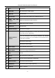


Table Of Contents
- Product Key Features
- Chapter 1 Introduction
- 1.1 Front Panel
- 1.2 IR Remote Control Operations
- 1.3 USB Mouse Operation
- 1.4 Rear Panel
- 1.4.1 DS-7100HQHI-K1, DS-7200HUHI-K (/P), iDS-7200HUHI-K/4S, DS-7200HTHI-K, DS-7200HQHI-K(/P), and iDS-7200HQHI-K/S
- 1.4.2 iDS-7200HQHI-K/S(B), iDS-7200HQHI-M/S and iDS-7200HQHI-M1/FA
- 1.4.3 iDS-7200HUHI-K/4S(B) and iDS-7200HUHI-M2/S
- 1.4.4 DS-7300HQHI-K
- 1.4.5 DS-7300HUHI/HTHI-K4, iDS-7316HUHI-K4/16S and DS-9000HUHI-K8
- 1.4.6 DS-7300HQHI/HUHI-K4, DS-8100HQHI/HUHI-K8, DS-9000HUHI-K8, and iDS-9016HUHI-K8/16S
- 1.4.7 DS-7200HGHI-K1
- 1.4.8 DS-7200HGHI-K2
- 1.4.9 DS-8100HTHI-K8
- 1.4.10 DS-9000HTHI-K8
- Chapter 2 Getting Started
- Chapter 3 Camera Management
- Chapter 4 Camera Settings
- Chapter 5 Live View
- Chapter 6 PTZ Control
- Chapter 7 Storage
- 7.1 Storage Device Management
- 7.2 Storage Mode
- 7.3 Recording Parameters
- 7.4 Configure Recording Schedule
- 7.5 Configure Continuous Recording
- 7.6 Configure Motion Detection Triggered Recording
- 7.7 Configure Event Triggered Recording
- 7.8 Configure Alarm Triggered Recording
- 7.9 Configure Picture Capture
- 7.10 Configure Holiday Recording and Capture
- 7.11 Configure Redundant Recording and Capture
- 7.12 Configure 1080p Lite
- Chapter 8 Disk Array
- Chapter 9 File Management
- Chapter 10 Playback
- Chapter 11 Event and Alarm Settings
- Chapter 12 POS Configuration
- Chapter 13 VCA Event Alarm
- 13.1 Human Body Detection
- 13.2 Face Detection
- 13.3 Vehicle Detection
- 13.4 Line Crossing Detection
- 13.5 Intrusion Detection
- 13.6 Region Entrance Detection
- 13.7 Region Exiting Detection
- 13.8 Unattended Baggage Detection
- 13.9 Object Removal Detection
- 13.10 Audio Exception Detection
- 13.11 Sudden Scene Change Detection
- 13.12 Defocus Detection
- 13.13 PIR Alarm
- Chapter 14 Smart Analysis
- Chapter 15 Human Body Detection
- Chapter 16 Face Picture Comparison
- Chapter 17 Network Settings
- Chapter 18 System Maintenance
- Chapter 19 General System Settings
- Chapter 20 Appendix

Network Video Recorder User Manual
54
No.
Item
Description
2
VIDEO OUT
BNC connector for video output.
3
LOOP OUT
RCA connector
4
USB Interface
Universal Serial Bus (USB) port for additional devices.
5
HDMI1 and VGA
Interface
HDMI1 and VGA video output interface.
6
HDMI2 Interface
HDMI2 video output interface.
7
AUDIO OUT
RCA connector.
8
Network Interface
Connector for network.
9
RS-485 and Alarm
Interface
Connector for RS-485 devices. T+ and T- pins connect to R+ and R-
pins of PTZ receiver respectively.
D+, D- pin connects to Ta, Tb pin of controller. For cascading
devices, the first DVR’s D+, D- pin should be connected with the D+,
D- pin of the next DVR.
Connector for alarm input.
Connector for alarm output.
10
Power Supply
100 to 240 VAC power supply.
11
Power Switch
Switch for turning on/off the device.
12
GND
Ground
13
LINE IN
BNC connector for audio input.
14
eSATA
Connects external SATA HDD, CD/DVD-RW.
15
RS-232 Interface
Connector for RS-232 devices.
16
ALARM OUT
Connector for alarm output (optional).
17
AUDIO IN
Audio in interface.