Network Video Recorder Quick Start Guide
Network Video Recorder Quick Start Guide TABLE OF CONTENTS Chapter 1 Panels Description ..................................................................................................... 9 1.1 Front Panel ............................................................................................................................... 9 1.1.1 iDS-96000NXI-I16(B) Series ............................................................................................. 9 1.1.2 iDS-96000NXI-I24(B) Series ...........
Network Video Recorder Quick Start Guide Chapter 5 Access by Web Browser ............................................................................................
Network Video Recorder Quick Start Guide Quick Start Guide COPYRIGHT © 2019 Hangzhou Hikvision Digital Technology Co., Ltd. ALL RIGHTS RESERVED. Any and all information, including, among others, wordings, pictures, graphs are the properties of Hangzhou Hikvision Digital Technology Co., Ltd. or its subsidiaries (hereinafter referred to be “Hikvision”).
Network Video Recorder Quick Start Guide Regulatory Information FCC Information Please take attention that changes or modification not expressly approved by the party responsible for compliance could void the user’s authority to operate the equipment. FCC compliance: This equipment has been tested and found to comply with the limits for a Class A digital device, pursuant to part 15 of the FCC Rules.
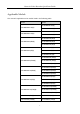
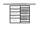
Network Video Recorder Quick Start Guide Applicable Models This manual is applicable to the models listed in the following table.
Network Video Recorder Quick Start Guide iDS-7716NXI-I4/16P/16S(B) iDS-7700NXI-I4/16P/16S(B) iDS-7732NXI-I4/16P/16S(B) iDS-7716NXI-I4/16P/X(B) iDS-7700NXI-I4/16P/X(B) iDS-7732NXI-I4/16P/X(B) iDS-7716NXI-I4/16S(B) iDS-7700NXI-I4/16S(B) iDS-7732NXI-I4/16S(B) iDS-7716NXI-I4/X(B) iDS-7700NXI-I4/X(B) iDS-7732NXI-I4/X(B) iDS-9608NXI-I8/4F(B) iDS-9600NXI-I8/4F(B) iDS-9616NXI-I8/4F(B) iDS-9632NXI-I8/4F(B) 6
Network Video Recorder Quick Start Guide Symbol Conventions The symbols that may be found in this document are defined as follows. Symbol Description Provides additional information to emphasize or supplement important points of the main text. Indicates a potentially hazardous situation, which if not avoided, could result in equipment damage, data loss, performance degradation, or unexpected results.
Network Video Recorder Quick Start Guide Use the device in conjunction with an UPS if possible. Power down the unit before connecting and disconnecting accessories and peripherals. A factory recommended HDD should be used for this device. Improper use or replacement of the battery may result in hazard of explosion. Replace with the same or equivalent type only. Dispose of used batteries according to the instructions provided by the battery manufacturer.
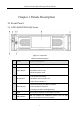
Network Video Recorder Quick Start Guide Chapter 1 Panels Description 1.1 Front Panel 1.1.1 iDS-96000NXI-I16(B) Series Figure 1-1 Front Panel Table 1-1 Panel Description No. Name Function Description 1 Locks or unlocks the panel by the key. Front Panel Lock Turn on/off device. 2 Power Button Solid blue: Device is on. Solid red: Device is off. Turn on/off alarm beep. 3 Mute Button Solid blue: Alarm sound is off. Unlit: Alarm sound is on. Solid red: At least one HDD is installed.
Network Video Recorder Quick Start Guide 7 HDD Sequence Indicator Shows the HDD sequence. 8 LCD 7-inch LCD for live-view image and menu operation. 1.1.2 iDS-96000NXI-I24(B) Series Figure 1-2 Front Panel Table 1-2 Panel Description No. Name Function Description 1 Locks or unlocks the panel by the key. Front Panel Lock Turn on/off device. 2 Power Button Solid blue: Device is on. Solid red: Device is off. 3 LCD 7-inch LCD for live-view image and menu operation.
Network Video Recorder Quick Start Guide 6 Alarm Indicator Solid red: Relay alarm occurs. USB Interface USB interface for additional devices such as USB mouse and USB Hard Disk Drive (HDD). 1.1.3 iDS-9600NXI-I8/8F(B), iDS-9600NXI-I8/X(B) and iDS-9600NXI-I8/16S(B) Series Figure 1-3 Front Panel Table 1-3 Panel Description No. Name Function Description 1 POWER Turns red when the power is connected but the system isn’t running; Turns blue when the power is connected and the system is running.
Network Video Recorder Quick Start Guide 7 Backup Back up video files. 1.1.4 iDS-9600NXI-I16/8F(B), iDS-9600NXI-I16/X(B) and iDS-9600NXI-I16/16S(B) Series Figure 1-4 Front Panel Table 1-4 Panel Description No. Name Description 1 Panel Lock Locks or unlocks the panel by the key. 2 Power Switch Powers on/off device. Solid blue indicates device is powered on. Solid red indicates device is shut down. Solid red: At least one HDD is installed 3 Status Indicator HDD Unlit: No HDD is detected.
Network Video Recorder Quick Start Guide During playback, press it to show/hide control panel. Confirms selection in any of the menu modes. Checks the checkbox fields. Switches on/off status. ENTER Plays or pauses the video playing in playback mode. Advances the video by a single frame in single-frame playback mode. Stops/starts auto switch in auto-switch mode. Control Button 5 Navigates between different fields and items in menus.
Network Video Recorder Quick Start Guide 2 POWER Turns white when the power is connected and the system is running. 3 Tx/Rx Flickers white when network connection is functioning properly. 4 IR Receiver Receiver for IR remote. 5 USB Interface Universal Serial Bus (USB) interface for additional devices such as USB mouse and USB Hard Disk Drive (HDD). 1.1.
Network Video Recorder Quick Start Guide Table 1-7 Panel Description No. Name Function Description POWER Turns red when the power is connected but the system is not running; turns blue when the power is connected and the system is running. ALARM Solid red indicates alarm occurs. Tx/Rx Flickers blue when network connection is functioning properly. Solid red: At least one HDD is installed. 1 HDD Unlit: No HDD is detected. Flashing red: HDD is reading/writing.
Network Video Recorder Quick Start Guide 1.2 Rear Panel 1.2.1 iDS-96000NXI-I16(B) and iDS-96000NXI-I24(B) Series Figure 1-8 iDS-96000NXI-I16(B) Series Rear Panel Figure 1-9 iDS-96000NXI-I24(B) Series Rear Panel Table 1-8 Panel Description No. Name Description 1 HDMI1/HDMI2 HDMI video output connector. 2 AUDIO OUT RCA connector for audio output. 3 USB 3.0 Interface Universal Serial Bus (USB) interface for additional devices such as USB mouse and USB Hard Disk Drive (HDD).
Network Video Recorder Quick Start Guide 7 RS-485 RS-485 interface. 8 KB Keyboard interface. 9 ALARM IN/OUT Connector for alarm input/output. 10 GND Ground (needs to be connected when NVR starts up). 11 Power Supply 100 to 240 VAC power supply. 12 AUDIO IN RCA connector for audio input. 13 eSATA Connects external SATA HDD, CD/DVD-RM. 14 VGA DB9 connector for VGA output. Display local video output and menu. 15 RS-232 Interface Connector for RS-232 devices.
Network Video Recorder Quick Start Guide 4 HDMI1/HDMI2 HDMI video output connector. 5 VGA1/VGA2 DB9 connector for VGA output. Display local video output and menu. 6 USB 3.0 Interface Universal Serial Bus (USB) interface for additional devices such as USB mouse and USB Hard Disk Drive (HDD). 7 RS-232 Interface Connector for RS-232 devices. 8 eSATA Connects external SATA HDD, CD/DVD-RM. Controller Port D+, D- pin connects to Ta, Tb pin of controller.
Network Video Recorder Quick Start Guide interfaces provided. 2 LINE IN RCA connector for audio input. 3 AUDIO OUT 2 RCA connectors for audio output. 4 HDMI1/HDMI2 HDMI video output connector. 5 VGA1/VGA2 DB9 connector for VGA output. Display local video output and menu. 6 USB 3.0 Interface Universal Serial Bus (USB) interface for additional devices such as USB mouse and USB Hard Disk Drive (HDD). 7 RS-232 Interface Connector for RS-232 devices.
Network Video Recorder Quick Start Guide Figure 1-13 iDS-7700NXI-I4/16P/16S(B) and iDS-7700NXI-I4/16P/X(B) Series Rear Panel Table 1-11 Panel Description No. Name Description 1 LAN Interface 1 network interface provided by iDS-7700NXI-I4/16P/16S(B) and iDS-7700NXI-I4/16P/X(B) series, and 2 network interfaces by iDS-7700NXI-I4/16S(B) and iDS-7700NXI-I4/X(B) series. 2 AUDIO OUT RCA connector for audio output. 3 LINE IN RCA connector for audio input. 4 HDMI HDMI video output connector.
Network Video Recorder Quick Start Guide 1.2.5 iDS-6700NXI-I/16S(B) and iDS-6700NXI-I/8F(B) Series 2 1 5 4 6 8 7 3 9 Figure 1-14 iDS-6700NXI-I/16S(B) Series Rear Panel Table 1-12 Panel Description Index Item Description 1 LAN1/LAN2 10M/100Mbps adaptive Ethernet interface. 2 LINE IN 3.5mm interface for line in; connect to audio input device or active pick-up, microphone, etc. 3 AUDIO OUT 3.5mm interface; connect to audio output device, e.g., loudspeaker, etc.
Network Video Recorder Quick Start Guide Figure 1-15 iDS-6700NXI-I/8F(B) Series Rear Panel Table 1-13 Panel Description Index Item Description 1 LINE IN 3.5mm interface for line in; connect to audio input device or active pick-up, microphone, etc. 2 RS-232 Serial interface for configuration of device’s parameters or used as transparent channel. 3 VGA DB9 connector for VGA output. Display local video output and menu. 4 Power Supply 12 VDC power supply. 5 SW SW dial switch. 6 USB 2.
Network Video Recorder Quick Start Guide 1.2.6 iDS-9600NXI-I8/4F(B) Figure 1-16 Rear Panel Table 1-14 Panel Description No. Name 1 LAN1/LAN2 interface 2 RJ45 10/100/1000 Mbps self-adaptive Ethernet interfaces provided. 2 AUDIO OUT 2 RCA connectors for audio output. 3 RS-232 Interface Connector for RS-232 devices. 4 VGA DB9 connector for VGA output. Display local video output and menu. 5 HDMI1/HDMI2 HDMI video output connector. 6 USB 3.
Network Video Recorder Quick Start Guide alarm output is triggered. If the device has 4 alarm outputs, the Ctrl 12V power is controled by alarm output 5. If the device has 8 alarm outputs, the Ctrl 12V power is controled by alarm output 9. Connect positive pole to number (1) of Ctrl 12V, and connect negative pole to G of Ctrl 12V. 11 DC 12V 12 VDC, 1 A power output for external device. Connect positive pole to number (1) of DC 12V, and connect negative pole to G of DC 12V.
Network Video Recorder Quick Start Guide Chapter 2 Installation and Connections 2.1 Installation During installation of the NVR: Use brackets for rack mounting. Ensure ample room for audio and video cables. When routing cables, ensure that the bend radius of the cables are no less than five times than its diameter. Connect the alarm cable. Allow at least 2cm (≈0.75-inch) of space between racks mounted devices. Ensure the NVR is grounded.
Network Video Recorder Quick Start Guide Step 2 To remove the cover from front panel, follow steps below: 1) Gently pull the cover out of the device along the direction arrow ① and make it a little above the left handle. The angle between the cover and the front panel must be within 10°. 2) Pull the front panel out of the device along the direction arrow ②. Handle with care to avoid damage.
Network Video Recorder Quick Start Guide Figure 2-4 Fix the Hard Disk Step 5 Push the dummy HDD back into the slot. Figure 2-5 Push the Dummy HDD into the Slot Step 6 Press the handle until you hear a click. Thus to fix the dummy HDD. Repeat above steps to install the rest dummy HDDs. Figure 2-6 Press the Handle Step 7 Install the cover back to front panel. And lock it with panel key.
Network Video Recorder Quick Start Guide 2.2.2 iDS-7700NXI-I4/(16P)/16S(B) Series Purpose: The following section introduces the HDD installation for the iDS-7700NXI-I4/16S(B) series and iDS-7700NXI-I4/16P/16S(B) series NVR. Take the example of iDS-7700NXI-I4/16S(B) to describe installation steps. Step 1 Remove the cover from the NVR by unfastening the screws on the rear and side panel. Figure 2-8 Remove Cover Step 2 Connect one end of the data cable to the motherboard of NVR and the other end to the HDD.
Network Video Recorder Quick Start Guide Figure 2-10 Connect Power Cable Step 4 Place the HDD on the bottom of the device and then fasten the screws on the bottom to fix the HDD. Figure 2-11 Fix Hard Disk 2.2.3 Other Series Purpose: Here we take the example of HDD installation of iDS-9600NXI-I8/8F(B) Series to describe the steps. Before you start: Disconnect the power from the NVR before installing a hard disk drive (HDD). A factory recommended HDD should be used for this installation.
Network Video Recorder Quick Start Guide Figure 2-12 Fasten Hard Disk Step 2 Insert the key and turn in clockwise direction to open the panel lock. Step 3 Press the buttons on the panel of two sides and open the front panel. Figure 2-13 Open Front Panel Step 4 Insert the hard disk along the slot until it is placed into position. Figure 2-14 Insert HDD to the Slot Step 5 Repeat the above steps to install other hard disks onto the NVR.
Network Video Recorder Quick Start Guide 2.3 Connections 2.3.1 Alarm Input Wiring The alarm input is an open/closed relay. To connect the alarm input to the device, use the following diagram. If the alarm input is not an open/close relay, please connect an external relay between the alarm input and the device. Figure 2-15 Alarm Input Wiring 2.3.
Network Video Recorder Quick Start Guide If you connect an AC load to the alarm output 3 of the NVR, then you must remove the JP 3 jumper. 2.3.3 Alarm Connection To connect alarm devices to the NVR: Step 1 Disconnect pluggable block from the ALARM IN /ALARM OUT terminal block. Step 2 Unfasten stop screws from the pluggable block, insert signal cables into slots and fasten stop screws. Ensure signal cables are tight. Step 3 Connect pluggable block back into terminal block. 2.3.
Network Video Recorder Quick Start Guide 2.4 HDD Storage Calculation Chart The following chart shows an estimation of storage space used based on recording at one channel for an hour at a fixed bit rate. Bit Rate Storage Used 96K 42M 128K 56M 160K 70M 192K 84M 224K 98M 256K 112M 320K 140M 384K 168M 448K 196M 512K 225M 640K 281M 768K 337M 896K 393M 1024K 450M 1280K 562M 1536K 675M 1792K 787M 2048K 900M 4096K 1.8G 8192K 3.6G 16384K 7.
Network Video Recorder Quick Start Guide Chapter 3 Menu Operation 3.1 Start up Your Device Proper startup and shutdown procedures are crucial to expanding the life of the NVR. To start your device: Step 1 Check the power supply is plugged into an electrical outlet. It is HIGHLY recommended that an Uninterruptible Power Supply (UPS) be used in conjunction with the device. The Power button on the front panel should be red, indicating the device is receiving the power.
Network Video Recorder Quick Start Guide We highly recommend you create a strong password of your own choosing (Using a minimum of 8 characters, including at least three of the following categories: upper case letters, lower case letters, numbers, and special characters.) in order to increase the security of your product. And we recommend you reset your password regularly, especially in the high security system, resetting the password monthly or weekly can better protect your product.
Network Video Recorder Quick Start Guide Figure 3-3 Draw the Pattern Connect at least 4 dots to draw the pattern. Each dot can be connected for once only. Step 3 Draw the same pattern again to confirm it. When the two patterns match, the pattern is configured successfully. If the two patterns are different, you must set the pattern again. 3.4 Log into the System Purpose: If the device has logged out, you must log in the device before operating the menu and other functions.
Network Video Recorder Quick Start Guide Figure 3-4 Login Interface Step 3 Input Password. Step 4 Click Login to log in. In the Login dialog box, if you enter the wrong password 7 times, the current user account will be locked for 60 seconds. 3.5 Enter Wizard to Configure Quick Basic Settings The Setup Wizard can walk you through some important settings of the device. By default, the Setup Wizard starts once the device has loaded. Check the checkbox to enable Setup Wizard when device starts.
Network Video Recorder Quick Start Guide 3.6 Network Settings Purpose: Network settings must be properly configured before you operate device over network. Step 1 Go to System > Network > TCP/IP. Figure 3-6 Network Settings Step 2 Select the General tab. Step 3 In the General Settings interface, you can configure the following settings: NIC Type, IPv4 Address, IPv4 Gateway, MTU and DNS Server.
Network Video Recorder Quick Start Guide Step 1 Click on the main menu bar to enter the Camera Management. Step 2 Click the Custom Add tab on the title bar to enter the Add IP Camera interface. Figure 3-7 Add IP Camera Step 3 Enter IP address, protocol, management port, and other information of the IP camera to add. Step 4 Enter the login user name and password of the IP camera. Step 5 Click Add to finish the adding of the IP camera.
Network Video Recorder Quick Start Guide Figure 3-8 Live View You can use the toolbar at the window bottom to realize the capture, instant playback, audio on/off, digital zoom, live view strategy, show information and start/stop recording, etc. 3.9 One-Touch RAID Configuration Purpose: The device supports the RAID storage function. Through one-touch configuration, you can quickly create the disk array. By default, the array type to be created is RAID 5. Before you start: Enable RAID function.
Network Video Recorder Quick Start Guide Step 3 Edit the array name in Array Name text filed and click OK to start configuring. If you install 4 or more HDDs, a hot spare disk for array rebuilding will be created. Step 4 A message box will pop up when the array creation is completed, click OK on it. Step 5 Optionally, the device will automatically initialize the created array. Go to Storage > RAID Setup > Array view the information of created arrray. 3.
Network Video Recorder Quick Start Guide Figure 3-10 Record Schedule Step 5 Select a day and click-and-drag the mouse on the time bar to set the record schedule. Step 6 Click Apply to save the settings. 3.11 Playback The recorded video files on the hard disk can be played back in the following modes: instant playback, all-day playback for the specified channel, and playback by normal/important/custom/event/smart/tag/sub-periods/external file search.
Network Video Recorder Quick Start Guide Figure 3-11 Playback Interface Step 4 Select the channel(s) to or execute simultaneous playback of multiple channels.
Network Video Recorder Quick Start Guide Chapter 4 Face Picture Comparison Purpose: The device supports the face picture comparison alarm and face capture for the connected camera based on face recognition feature. The chapter is only available for iDS-9600NXI-I16/8F(B), iDS-9600NXI-I8/8F(B), iDS-9600NXI-I8/4F(B), iDS-96000NXI-I16(B) and iDS-96000NXI-I24(B) series. Step 1 Go to Smart Analysis > Face Picture Database. Step 2 Add the face picture library to the device with the face pictures uploaded.
Network Video Recorder Quick Start Guide Chapter 5 Access by Web Browser You shall acknowledge that the use of the product with Internet access might be under network security risks. For avoidance of any network attacks and information leakage, please strengthen your own protection. If the product does not work properly, please contact with your dealer or the nearest service center. Purpose: You can get access to the device via web browser.
Network Video Recorder Quick Start Guide If the device is already activated, enter the user name and password in the login interface, and click the Login button. Figure 5-2 Login Step 3 Install the plug-in before viewing the live video and managing the camera. Please follow the installation prompts to install the plug-in. You may have to close the web browser to finish the installation of the plug-in.
UD14326B