
Quick Start Guide
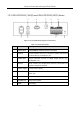


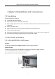


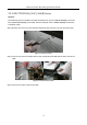
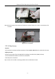
Table Of Contents
- Chapter 1 Panels Description
- 1.1 Front Panel
- 1.1.1 iDS-96000NXI-I16(B) Series
- 1.1.2 iDS-96000NXI-I24(B) Series
- 1.1.3 iDS-9600NXI-I8/8F(B), iDS-9600NXI-I8/X(B) and iDS-9600NXI-I8/16S(B) Series
- 1.1.4 iDS-9600NXI-I16/8F(B), iDS-9600NXI-I16/X(B) and iDS-9600NXI-I16/16S(B) Series
- 1.1.5 iDS-7700NXI-I4(/16P)/16S(B) and iDS-7700NXI-I4(/16P)/X(B) Series
- 1.1.6 iDS-6700NXI-I/8F(B) and iDS-6700NXI-I/16S(B) Series
- 1.1.7 iDS-9600NXI-I8/4F(B)
- 1.2 Rear Panel
- 1.2.1 iDS-96000NXI-I16(B) and iDS-96000NXI-I24(B) Series
- 1.2.2 iDS-9600NXI-I8/8F(B), iDS-9600NXI-I8/X(B) and iDS-9600NXI-I8/16S(B) Series
- 1.2.3 iDS-9600NXI-I16/8F(B), iDS-9600NXI-I16/X(B) and iDS-9600NXI-I16/16S(B) Series
- 1.2.4 iDS-7700NXI-I4(/16P)/16S(B) and iDS-7700NXI-I4(/16P)/X(B) Series
- 1.2.5 iDS-6700NXI-I/16S(B) and iDS-6700NXI-I/8F(B) Series
- 1.2.6 iDS-9600NXI-I8/4F(B)
- 1.1 Front Panel
- Chapter 2 Installation and Connections
- Chapter 3 Menu Operation
- Chapter 4 Face Picture Comparison
- Chapter 5 Access by Web Browser

Network Video Recorder Quick Start Guide
20
Figure 1-13 iDS-7700NXI-I4/16P/16S(B) and iDS-7700NXI-I4/16P/X(B) Series Rear Panel
Table 1-11 Panel Description
No.
Name
Description
1
LAN Interface
1 network interface provided by
iDS-7700NXI-I4/16P/16S(B) and
iDS-7700NXI-I4/16P/X(B) series, and 2 network
interfaces by iDS-7700NXI-I4/16S(B) and
iDS-7700NXI-I4/X(B) series.
2
AUDIO OUT
RCA connector for audio output.
3
LINE IN
RCA connector for audio input.
4
HDMI
HDMI video output connector.
5
USB 3.0 Interface
Universal Serial Bus (USB) interface for
additional devices such as USB mouse and USB
Hard Disk Drive (HDD).
6
RS-232 Interface
Connector for RS-232 devices.
7
VGA
DB9 connector for VGA output. Display local
video output and menu.
8
RS-485 Interface
Half-duplex connector for RS-485 devices.
9
ALARM IN
Connector for alarm input.
ALARM OUT
Connector for alarm output.
10
GND
Ground (needs to be connected when NVR
starts up).
11
Power Supply
100 to 240 VAC power supply.
12
Power Switch
Switch for turning on/off the device.
13
Network Interface with PoE
function
Network interface for the cameras and to
provide power over Ethernet.
14
eSATA Interface
Connects external SATA HDD, CD/DVD-RM.
15
VIDEO OUT
BNC connector for video output.