
Quick Start Guide
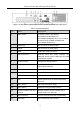
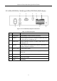
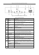
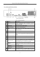
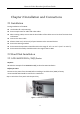
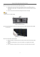
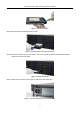
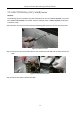
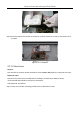
Table Of Contents
- Chapter 1 Panels Description
- 1.1 Front Panel
- 1.1.1 iDS-96000NXI-I16(B) Series
- 1.1.2 iDS-96000NXI-I24(B) Series
- 1.1.3 iDS-9600NXI-I8/8F(B), iDS-9600NXI-I8/X(B) and iDS-9600NXI-I8/16S(B) Series
- 1.1.4 iDS-9600NXI-I16/8F(B), iDS-9600NXI-I16/X(B) and iDS-9600NXI-I16/16S(B) Series
- 1.1.5 iDS-7700NXI-I4(/16P)/16S(B) and iDS-7700NXI-I4(/16P)/X(B) Series
- 1.1.6 iDS-6700NXI-I/8F(B) and iDS-6700NXI-I/16S(B) Series
- 1.1.7 iDS-9600NXI-I8/4F(B)
- 1.2 Rear Panel
- 1.2.1 iDS-96000NXI-I16(B) and iDS-96000NXI-I24(B) Series
- 1.2.2 iDS-9600NXI-I8/8F(B), iDS-9600NXI-I8/X(B) and iDS-9600NXI-I8/16S(B) Series
- 1.2.3 iDS-9600NXI-I16/8F(B), iDS-9600NXI-I16/X(B) and iDS-9600NXI-I16/16S(B) Series
- 1.2.4 iDS-7700NXI-I4(/16P)/16S(B) and iDS-7700NXI-I4(/16P)/X(B) Series
- 1.2.5 iDS-6700NXI-I/16S(B) and iDS-6700NXI-I/8F(B) Series
- 1.2.6 iDS-9600NXI-I8/4F(B)
- 1.1 Front Panel
- Chapter 2 Installation and Connections
- Chapter 3 Menu Operation
- Chapter 4 Face Picture Comparison
- Chapter 5 Access by Web Browser

Network Video Recorder Quick Start Guide
24
alarm output is triggered.
If the device has 4 alarm outputs, the Ctrl 12V power is
controled by alarm output 5.
If the device has 8 alarm outputs, the Ctrl 12V power is
controled by alarm output 9.
Connect positive pole to number (1) of Ctrl 12V, and
connect negative pole to G of Ctrl 12V.
11
DC 12V
12 VDC, 1 A power output for external device.
Connect positive pole to number (1) of DC 12V, and
connect negative pole to G of DC 12V.
12
GND
Ground (needs to be connected when NVR starts up).
13
Power Switch
Switch for turning on/off the device.
14
Power Supply
100 to 240 VAC power supply.
15
VIDEO OUT
BNC connector for video output.
16
LINE IN
RCA connector for audio input.