User Manual of Network Traffic Camera Network Traffic Camera User Manual 0
Network Traffic Camera User Manual User Manual COPYRIGHT ©2019 Hangzhou Hikvision Digital Technology Co., Ltd. ALL RIGHTS RESERVED. Any and all information, including, among others, wordings, pictures, graphs are the properties of Hangzhou Hikvision Digital Technology Co., Ltd. or its subsidiaries (hereinafter referred to be “Hikvision”).
Network Traffic Camera User Manual Regulatory Information FCC Information Please take attention that changes or modification not expressly approved by the party responsible for compliance could void the user’s authority to operate the equipment. FCC compliance: This equipment has been tested and found to comply with the limits for a digital device, pursuant to part 15 of the FCC Rules.
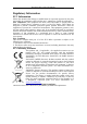
Network Traffic Camera User Manual Symbol Conventions The symbols that may be found in this document are defined as follows. Symbol Description Note Provides additional information to emphasize or supplement important points of the main text. Indicates a potentially hazardous situation, which if not avoided, could result in equipment damage, data loss, performance degradation, or unexpected results.
Network Traffic Camera User Manual beam. Do not place the camera in extremely hot, cold temperatures (the operating temperature should be between -30°C ~ 70°C), dusty or damp environment, and do not expose it to high electromagnetic radiation. To avoid heat accumulation, good ventilation is required for a proper operating environment. Keep the camera away from water and any liquid. While shipping, the camera should be packed in its original packing.
Network Traffic Camera User Manual Table of Contents Chapter 1 System Requirement .............................................................................. 7 Chapter 2 Network Connection .............................................................................. 8 2.1 Wire over the LAN ............................................................................................... 8 2.2 Activate the Camera............................................................................................
Network Traffic Camera User Manual Chapter 10 Text Overlay Configuration ............................................................. 42 10.1 Configure Single Picture Overlay ........................................................................ 42 10.2 Configure Text Overlay on Video ........................................................................ 45 Chapter 11 Capture Parameters Configuration ................................................. 47 11.1 Configure Flash Light Parameters ..
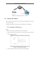
Network Traffic Camera User Manual Chapter 1 System Requirement Operating System: Microsoft Windows XP SP1 and above version/Vista/Win 7/Win 10/Server 2003/Server 2008 32bits CPU: 1.0 GHz or higher RAM: 1G or higher Display: 1024×768 resolution or higher Web Browser: Internet Explorer 8.0 and above version, and Google Chrome 36.
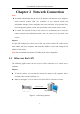
User Manual of Network Traffic Camera Chapter 2 Network Connection Note: You shall acknowledge that the use of the product with Internet access might be under network security risks. For avoidance of any network attacks and information leakage, please strengthen your own protection. If the product does not work properly, please contact with your dealer or the nearest service center. To ensure the network security of the camera, we recommend you to have the camera assessed and maintained termly.
Network Traffic Camera User Manual Switch Computer Traffic Camera Figure 2-2 Connecting via a Switch or a Router 2.2 Activate the Camera You are required to activate the camera first by setting a strong password for it before you can use the camera. Activation via Web Browser and Activation via SADP Software are supported. 2.2.1 Activation via Web Browser Steps: 1. Power on the camera, and connect the camera to the network. 2.
Network Traffic Camera User Manual STRONG PASSWORD RECOMMENDED– We highly recommend you create a strong password of your own choosing (using a minimum of 8 characters, including upper case letters, lower case letters, numbers, and special characters) in order to increase the security of your product. And we recommend you reset your password regularly, especially in the high security system, resetting the password monthly or weekly can better protect your product. 4. Confirm the password. 5.
Network Traffic Camera User Manual 4. Click Activate to activate the device. STRONG PASSWORD RECOMMENDED– We highly recommend you create a strong password of your own choosing (using a minimum of 8 characters, including upper case letters, lower case letters, numbers, and special characters) in order to increase the security of your product. And we recommend you reset your password regularly, especially in the high security system, resetting the password monthly or weekly can better protect your product.
User Manual of Network Traffic Camera Chapter 3 Login Steps: 1. Open the web browser. 2. In the browser address bar, input the IP address of the camera, and press the Enter key to enter the login interface. 3. Input User Name and Password. 4. Click Login. The admin user should configure the device accounts and user/operator permissions properly. Delete the unnecessary accounts and user/operator permissions. Figure 3-1 Login Interface 5.
User Manual of Network Traffic Camera Chapter 4 Live View 4.1 Live View Page Purpose: The live view page allows you to view the real-time video and capture images. Log in to the camera to enter the live view page, or you can click Live View on the menu bar of the main page to enter the live view page.
Network Traffic Camera User Manual adjust the volume, enable/disable two-way audio, capture, record, enable/disable digital zoom, etc. Refer to the following table for the description of the icons on the live view page. Table 4-1 Descriptions of Live View Icons Icon Description Start/Stop live view. / The window size is 4:3. The window size is 16:9. The original widow size. Self-adaptive window size. Live view with main stream. Live view with sub-stream. Live view with third stream.
Network Traffic Camera User Manual to exit the regional focus operation mode. Digital zoom: Click to enable digital zoom function and the icon turns into . Then drag the mouse towards low right direction to draw a rectangle on the image as the desired zoom. After viewing it you can click any place of the picture to get back to normal picture. 4.2 Start Live View On the live view page, click on the toolbar to start the live view of the camera. 4.
Network Traffic Camera User Manual Figure 4-2 Live Status and Traffic Statistics As displayed on the figure above, the picture area can be divided into three parts: scene shot area, digital zoom area, license plate area. Arm the camera: Level 1 Arming, Level 2 Arming, and Disarming are selectable. Level 1 Arming: The camera is allowed to connect to only one data storage device for image and information uploading.
Network Traffic Camera User Manual Figure 4-3 Picture List Table 4-2 Description of Picture List Parameters Item Description No. Picture No. Capture Time The time of capturing the picture with millisecond precision. For example, 20171011143350933 means the picture is captured at 14:33:50:933, on October 11th, in 2017. Lane No. The lane where the vehicle is captured. License Plate No. The license plate number of the vehicle. Vehicle No. The vechile counting No. ranging from 1 to 65535.
User Manual of Network Traffic Camera Chapter 5 Picture Search Purpose: The captured picture of all types, including normal, overspeed, wrong-way driving, etc., can be searched from this page. You can also export the pictures to the PC local directory. Before you start: Please insert a memory card in the camera for picture storage. Steps: 1. Click Picture on the menu bar to enter picture searching page. Figure 5-1 Picture Searching 2.
User Manual of Network Traffic Camera Chapter 6 Log Search Purpose: The operation, alarm, exception and information of the camera can be stored in log files. You can also export the log files on your demand. Before you start: Please configure network storage for the camera or insert a memory card in the camera. Steps: 1. Click Log on the menu bar to enter log searching page. Figure 6-1 Log Searching 2.
User Manual of Network Traffic Camera Chapter 7 Local Configuration Purpose: You can configure the live view parameters, recording files settings, and picture settings from this page. Note: The record files and captured pictures are the ones you record and captured using the web browser and thus the saving paths of them are on the PC running the browser. Enter the local configuration page: Configuration > Local Configuration. Figure 7-1 Local Configuration Steps: 1.
Network Traffic Camera User Manual Live View Performance: Set the live view performance to Real-time, Balanced or Fluent. Rules: Enable or disable rules. If you enable rules, when there is vehicle passing, a tracking frame will appear in the live view. Pos Info: Enable the function, feature information of the detected target is dynamically displayed near the target in the live image. Record File Settings: Set the manual recorded video parameters.
User Manual of Network Traffic Camera Chapter 8 System Configuration Purpose: You can configure the parameters on this page, including device information, serial ports, network parameters, time configuration, service, etc. 8.1 View Device Information Go to the device information page to check the device information: Configuration > Device Configuration > System Configuration > Device Information. Device Name and Device No. can be changed as desired.
Network Traffic Camera User Manual Figure 8-1 Device Information 8.2 Configure Installation Parameters You can set the installation parameters of the camera. These parameters are designed for speed detection. Steps: 1. Go to Configuration > Device Configuration > System Configuration > Installation Parameters.
Network Traffic Camera User Manual Figure 8-2 Installation Parameters 2. Set the installation parameters according to the actual conditions. Installation height and horizontal distance can be set according to the actual installation height. Horizontal field angel and vertical field angel refer to the installation angel of the camera. You can set the degrees manually according to the actual installation angel. 3. Click Save to save the settings. 8.
Network Traffic Camera User Manual serial device will be controlled remotely by the computer through the network. Steps: 1. Go to Configuration > Device Configuration > System Configuration > Serial Ports. Figure 8-3 Serial Ports Settings 2. Configure the RS-485 and RS-232 parameters. 3. Click Save to save the settings. 8.4 Configure TCP/IP Settings Purpose: TCP/IP settings must be properly configured before you operate the camera over network. Steps: 1.
Network Traffic Camera User Manual Figure 8-4 Network Parameters 2. Configure the following parameters. NIC Settings Configure the NIC parameters, including the NIC Type, IPv4 Address, IPv4 Subnet Mask, IPv4 Default Gateway, IPv6 Mode, IPv6 Address, IPv6 Subnet Mask, IPv6 Default Gateway, MAC Address (read-only), MTU settings (read-only), Multicast Address, Alarm Management Host Address/Port, ANPR IP address, ANPR port, Alarm Host Address, and Alarm Host Port.
Network Traffic Camera User Manual from the multicast group address. Before utilizing this function, you have to enable the Multicast function of your router. ● Number plate data can be transmitted through ANPR protocol. Before using this function, you have to configure ANPR IP address and ANPR port to connect the host. DNS Server Configuration DNS (Domain Name System) is a network system used to translate names into IP address. 3. Click Save to save the settings. 8.
Network Traffic Camera User Manual 8.6 Configure HTTPS Purpose: HTTPS provides authentication of the web site and associated web server that one is communicating with, which protects against Man-in-the-middle attacks. Perform the following steps to set the port number of https. Example If you set the port number as 443 and the IP address is 192.168.1.64, you may access the device by inputting https://192.168.1.64:443 via the web browser. Note: The HTTPS port can be only configured through the web browser.
Network Traffic Camera User Manual Figure 8-7 Create Private Certificate 3) Enter the parameters. 4) Click OK to save the settings. OPTION 2: Signed certificate is available. Start the installation directly. 1) Click Signed certificate is available. Start the installation directly. 2) Click View to find the saving path of the certificate. 3) Click Install to install the certificate. OPTION 3: Create the certificate request first and continue the installation.
Network Traffic Camera User Manual 8.7 Configure Time You can follow the instructions in this section to configure the time synchronization and DST settings. Time Settings Steps: 1. Go to Configuration > Device Configuration > System Configuration> Time. 2. Select the time zone of your region. 3. You can adjust time manually. Or you can enable NTP (National Time Protocol) to synchronize time of your camera to the configured NTP server.
Network Traffic Camera User Manual Steps: 1. Select Synchronization Mode as NTP Synchronization. Figure 8-9 NTP Synchronization 2. Configure the following settings: Server Address: IP address of NTP server. NTP Port: Port of NTP server. Interval: The time interval between the two synchronizing actions with NTP server. Note: If the camera is connected to a public network, you should use a NTP server that has a time synchronization function, such as the server at the National Time Center (IP Address: 210.
Network Traffic Camera User Manual Figure 8-10 DST Settings 8.8 Enable User Lock Steps: 1. Go to Configuration > Device Configuration > System Configuration> Service. Figure 8-11 Service Configuration 2. Check Enable User Lock or Enable SSH Service to enable the function. 3. Click Save to save the settings.
Network Traffic Camera User Manual Chapter 9 Encoding and Storage Configuration Purpose: You can configure the encoding and storage related parameters from this page, including video encoding, image encoding, ROI, record schedule, redundant storage, and FTP. 9.1 Configure Video Encoding Steps: 1. Go to Configuration >Device Configuration > Encoding and Storage > Video Encoding. Figure 9-1 Video Encoding 2.
Network Traffic Camera User Manual Stream Type: Video and Video & Audio are selectable. Max. Bitrate: Set the max. bitrate to 32 to 16384 Kbps, or custom. The higher value corresponds to the higher video quality, and the higher bandwidth is required. Note: The maximum limit of the max. bitrate value varies according to different cameras. For some certain cameras, the maximum limit is 8192 Kbps or 12288 Kbps. Frame Rate: The range of frame rate varies according to different video standard.
Network Traffic Camera User Manual 9.2 Configure Image Encoding Steps: 1. Go to Configuration >Device Configuration > Encoding and Storage > Image Encoding. Figure 9-2 Image Encoding 2. Select Capture Resolution. 3. Enter JPEG Picture Size. The captured pictures are saved as JPEG files, and you can define the picture size by manually entering the value. 4. Click Save to save the settings. 9.
Network Traffic Camera User Manual Figure 9-3 ROI Settings 2. Select Stream Type for ROI encoding. This camera model supports main stream and sub stream. 3. Check Enable under Fixed Area item. 4. Select Area Code from the drop-down list for ROI settings. There are four fixed areas selectable. 5. Click Draw Area, and then drag the mouse to draw the region of interest on the live video. 6. Select ROI Level to set the image quality enhancing level.
Network Traffic Camera User Manual 9.4 Configure Record Schedule Purpose: You can follow the instructions to configure the scheduled recording. By default, the record files of scheduled recording are stored in the microSD card. The max. storage space is 128 G. Steps: 1. Go to Configuration > Device Configuration > Encoding and Storage > Record Schedule. Figure 9-4 Record Schedule Configuration 2. Select Record Stream. 3. (Optional) Check Enable Recording Overwriting.
Network Traffic Camera User Manual Figure 9-5 Edit Record Schedule 1) Select the day to set the record schedule. 2) Set all-day record or segment record. If you want to configure the all-day recording, check the All Day checkbox. If you want to record in different time sections, check the Customize checkbox. Set the Start Time and End Time. Notes: The time of each segment cannot be overlapped. Up to 4 segments can be configured. The default record type is Normal and you cannot edit it.
Network Traffic Camera User Manual Redundant Storage. Figure 9-6 Redundant Storage Configuration 2. View the HDD information such as Capacity, Free Space, Status, etc. 3. (Optional) Check the HDD and click Format to format it. 4. (Optional) Check Auto-Initialize Redundant Storage. Then the TF card in the redundant storage can be formatted automatically. The storage is used for store captured pictures, traffic violation video, and log. 5. (Optional) Check Auto-Upload Data in Redundant Storage. 6.
Network Traffic Camera User Manual We have three ways to storage data (priority ranking from prior to less prior): FTP, SDK arming and local memory card storage. If FTP is enabled, the SDK arming and local memory card storage are invalid. If SDK arming is enabled, memory card storage is invalid. Steps: 1. Go to Configuration > Device Configuration > Encoding and Storage > FTP. Figure 9-7 FTP Configurations 2. Check Upload Additional Information to FTP to enable the uploading function. 3.
Network Traffic Camera User Manual 4) Select the content in different directories. For the Parent Directory, you can select Device Name, Device No., and Device IP Address. For the Level 2/3/4 Directory, you can select Camera Name, Camera No., Device IP Address, etc. 4. Configure the Name Rule. 1) Select the Separator. 2) Select the Elements of each name. Figure 9-9 Name Rule Configuration 5. Configure the OSD Information. 6. Figure 9-10 OSD Information Click Save to save the settings.
Network Traffic Camera User Manual Chapter 10 Text Overlay Configuration Purpose: Configure the OSD on the captured pictures and videos. 10.1 Configure Single Picture Overlay Purpose: You can configure the overlay information of the captured single picture. Steps: 1. Go to Configuration > Device Configuration > Text Overlay > Single Picture Overlay. Figure 10-1 Single Picture Overlay 2. Check Capture Picture Overlay. 3. Configure the parameters below.
Network Traffic Camera User Manual Background Color: the background color of the overlay information. 4. Set the overlay text position. Overlay on Picture: Display the information on the picture. Figure 10-2 Overlay on Picture Overlay Above the Picture: Display the information on the top. Figure 10-3 Overlay Above the Picture Overlay Below the Picture: Display the information on the bottom.
Network Traffic Camera User Manual Figure 10-4 Overlay Below the Picture 5. (Optional) Check Overlay Number Zeroizing. 6. (Optional) Check Overlay Plate Close-up on the captured picture. 7. Configure the overlay information. Figure 10-5 Configure Display Information 1) Check the overlay information or check Select All to display all the overlay information. 2) Configure the overlay information. Overlay Information: You can edit the details of the overlay information type.
Network Traffic Camera User Manual displayed together. Space: It stands for the length of blank space between the last character of the first item and the first character of the next item. Line Break Characters: When you add Line Break Characters to an item, the item is displayed as a new paragraph, and the number stands for the scale of space above the paragraph. / : Click to move the overlay position up. Click to move the overlay position down. E.g.
Network Traffic Camera User Manual Figure 10-7 OSD on Video 2. Select the OSD Properties. 3. Select the OSD Font Size. 4. Configure the parameters below according to your needs. Check Camera Name and edit the name in the text field. Configure date. 1) Check Display Date. 2) Select the Time Format. 3) Select the Date Format. 4) Check Display Week. 5) Check Display Millisecond. Check Display Item and edit the custom content in the corresponding text fields. 5.
Network Traffic Camera User Manual Chapter 11 Capture Parameters Configuration Purpose: You can configure flash light and vehicle feature on this page. 11.1 Configure Flash Light Parameters Steps: 1. Go to Configuration > Device Configuration > Capture Parameters > Flash Light Parameters. 2. Select a tab corresponded with the flash light control port. The camera supports IO:1 and IO: 2. IO:1 is the built-in flash light. IO:2 is the extra flash light. Figure 11-1 Flash Light Parameters Configuration 3.
Network Traffic Camera User Manual and end time. 4. (Optional) Copy settings of current port to other ports by checking desired port number. 5. Click Save to save the settings. 11.2 Configure Vehicle Feature Steps: 1. Go to Configuration > Device Configuration > Capture Parameters > Vehicle Feature. Figure 11-2 Vehicle Feature Configuration 2. Check Vehicle Color Recognition or Enable Car Logo Recognition to enable the functions. 3. Click Save to save the settings.
Network Traffic Camera User Manual Chapter 12 Image Parameters Configuration Purpose: Configure double shutter parameters, general parameters, video parameters, and ICR on this page. 12.1 Configure General Parameters Purpose: General parameters refer to the image parameters applying to both video image and capture image, such as saturation, sensitivity, lens type, sharpness, white balance, gamma correction, and brightness enhancement. Steps: 1.
Network Traffic Camera User Manual White Balance is the white rendition function of the camera used to adjust the color temperature according to the environment. The white balance can be set to Auto WB1, Auto WB2, Fluorescent Light, Incandescent Light, Warm Light, and Natural Light. 3. Select WDR mode. On, Time and Brightness are selectable. Wide Dynamic Range is used when there is a high contrast of the bright area and the dark area of the scene. Time: Activate WDR function on schedule.
Network Traffic Camera User Manual The camera supports dual-shutter. One shutter for video image and the other one for capture image. You can configure shutter parameters for video image. Steps: 1. Go to Configuration > Device Configuration > Image Parameters > Video. Figure 12-2 Video Image Configuration 2. Adjust Brightness [0 to100]. Brightness describes bright of the image, which ranges from 1 to 100. 3. Adjust Contrast [0 to 100].
Network Traffic Camera User Manual 1) If you select Normal Mode, adjust 3D DNR Level from 0 to 100. 2) If you select Expert Mode, adjust Spatial Intensity and Time Intensity from 0 to 100. 7. (Optional) Check 2D DNR, and adjust 2D DNR Level from 0 to 100. 8. (Optional) Check Slow Shutter and select slow shutter level. In slow shutter mode, the shutter speed will automatically decrease in low illumination conditions to maintain clear video images by increasing the exposure time.
Network Traffic Camera User Manual 2. Check Enable License Plate Enhancement. Level adjustable from 0 to 100. 3. Check Contrast Enhancement. 1) Select mode as On, Time, Brightness. Time: Activate the function on schedule. Set the start time and end time. Brightness: Active the function automatically. Set the brightness threshold. 2) Set enhancement level from 0 to 100. Higher value means stronger effect. 3) Set Halo Suppression Level from 0 to 100. Higher value means stronger effect. 12.
Network Traffic Camera User Manual Scheduled Switch: The ICR switches according to the configured time schedule. Figure 12-6 Scheduled Switch 3. Click Save to save the settings.
Network Traffic Camera User Manual Chapter 13 Entrances and Exits Configuration Purpose: You can configure the vehicle whitelist and blacklist, and import, export, add, edit, delete, or search the list. Before you start: Make sure the TF card is installed for the camera and can work normally. Note: The whitelist and blacklist function can be used normally only after the TF card is installed and works normally, or selecting the 8 GB model device. Steps: 1.
Network Traffic Camera User Manual 3) Edit the whitelist and blacklist information according to the template and save it locally. Note: You must edit the whitelist and blacklist information according to the template, or the import will fail. 4) Click to select the file directory of the saved list. 5) Click Import to import the list to the camera. Figure 13-3 Import Completed Note: Up to 6000 items of whitelist and blacklist can be imported once.
Network Traffic Camera User Manual 4. 5. 6. 7. 3) Click OK to add it and it will be listed on the table. Edit the added whitelist/blacklist vehicle information. 1) Select an item from the table and click Edit. Figure 13-6 Edit Whitelist/Blacklist Vehicle Information 2) Edit the information. 3) Click OK to save the settings. Export the whitelist/blacklist list. 1) Click Export. 2) Select the local path to save the list. 3) Click OK to export the list. Search the whitelist/blacklist vehicle information.
Network Traffic Camera User Manual Chapter 14 Application Mode Configuration Purpose: This chapter introduces the parameters configuration under different trigger mode. The supported trigger modes vary according to the camera models. Note: The trigger modes below are for reference only. The trigger modes of the actual device prevail. 14.1 Smart Mode In this mode, target capture and license plate recognition are trigger by internal live video analysis. Steps: 1.
Network Traffic Camera User Manual 4. Select Capture Type. All and Motor Vehicle are selectable. All: capture and recognize pedestrian, non-motor vehicle and motor vehicle. Motor Vehicle: capture and recognize motor vehicle. 5. Draw LPR area. 1) Click Draw LPR Area. 2) (3 lanes for instance) Adjust the position and length of Lane Line 1, Lane Line 2, Lane Line 3, and Lane Right Border. Notes: ● When drawing lines, you should avoid the overlap among lanes.
Network Traffic Camera User Manual 3. Select Total Lanes. Only 1 lane is selectable. Figure 14-3 License Plate Recognition System Configuration 4. Select Trigger Type. Vehicle Detection, I/O Coil, and RS-485 are selectable. Vehicle Detection 1) Select Picture Mode. Scene Picture and Scene Picture + Close-up Picture are selectable. 2) (Optional) Check Capture Plate Absence Vehicle to capture the vehicle without license plate. 3) Select Capture Mode. Strobe Light Mode is selectable.
Network Traffic Camera User Manual 4) Select I/O No. When the coil detects that there is vehicle passing, a rising or falling edge signal is sent to the linked I/O of the capture unit to trigger capture. Note: The I/O Trigger Default Status and I/O No. should be configured according to the actual conditions. RS-485 1) Select Picture Mode. Scene Picture and Scene Picture + Close-up Picture are selectable. 2) Enter the Linked Lane No. ranging from 1 to 99. The lane No.
Network Traffic Camera User Manual 6. (Optional) Click Get Recommended Value to get the recommended value of the parameters. 7. Click Save to save the settings.
Network Traffic Camera User Manual Chapter 15 Exception Purpose: The exception type can be HDD error, network disconnected, IP address conflicted, and vehicle detector exception. Steps: 1. Go to Configuration > Device Configuration> Exception. 2. Select the exception type and the corresponding trigger methods. Figure 15-1 Exception Settings Notify Surveillance Center Send an exception or alarm signal to remote management software when an event occurs.
Chapter 16 Maintenance 16.1 Check Device Status Purpose: You can check the device status. Steps: 1. Go to Configuration > Device Status. Figure 16-1 Device Status 2. View Device IP Address and Device Status. Device IP Address: Display the current IP address of the camera. Device Status: Detailed descriptions are shown in the following table. Table 16-1 Description of Device Status Item Description Live View Connection The current number of established live view connection.
Go to Configuration >Device Configuration> User Management. Figure 16-2 User Management 16.2.1 Add a User The admin user has all permissions by default and can create/modify/delete other accounts. The admin user cannot be deleted and you can only change the admin password. Steps: 1. Click Add to add a user. 2. Select User Type. 3. Enter User Name and Password.
uncheck the permissions for the new user. 6. Click OK to add the user. Figure 16-3 Add a User 16.2.2 Modify a User Steps: 1. Select a user from the list and click Edit. 2. Modify the editable parameters.
Figure 16-4 Modify Admin Figure 16-5 Modify Operator/User 3. Click OK to save the settings. 16.2.3 Delete a User Steps: 1. Select the user you want to delete and click Delete. 2. Click OK on the pop-up message box to delete the user. 16.3 Reboot the Camera Steps: 1. Go to Configuration > Device Configuration > System Maintenance > Reboot. 2. Click Reboot to reboot the camera.
16.4 Restore Default Settings Steps: 1. Go to Configuration > Device Configuration > System Maintenance > Default. 2. Click Soft Reset or Hard Reset to restore default settings. Figure 16-7 Restore Default Settings Note: Use the Hard Reset function with caution. 16.5 Export Debug File Steps: 1. Go to Configuration > Device Configuration > System Maintenance > Debug File Export. Figure 16-8 Export Debug File 2. Click Debug File Export and set the saving path to save the debug file in local storage.
Export Configuration File. Figure 16-9 Export Configuration File 2. Click Export and set the saving path to save the configuration file in local storage. 16.7 Import Configuration File Purpose: Configuration file is used for the batch configuration of the camera, which can simplify the configuration steps when there are a lot of cameras needing configuration. Steps: 1. Go to Configuration > Device Configuration > System Maintenance > Import Configuration File. Figure 16-10 Import Configuration File 2.
1. Go to Configuration > Device Configuration > System Maintenance > Import Configuration File. Figure 16-11 Upgrade 2. Click Browse to select the ALG file, and click Import to import the ALG file. 3. Go to Configuration > Device Configuration > System Maintenance > Upgrade. 4. Click Browse to select the local upgrade file. 5. Click Upgrade to start upgrade. Note: ALG file importing is optional. Please operate according to situations. The upgrading process will take 1~10 minutes.
Appendix SADP Software Introduction Description of SADP SADP (Search Active Devices Protocol) is a kind of user-friendly and installation-free online device search tool. It searches the active online devices within your subnet and displays the information of the devices. You can also modify the basic network information of the devices using this software.
you can click to expand the device table and hide the network parameter panel on the right side, or click to show the network parameter panel. Modify network parameters Steps: 1. Select the device to be modified in the device list and the network parameters of the device will be displayed in the Modify Network Parameters panel on the right side. 2. Edit the modifiable network parameters, e.g. IP address and port number. 3.
Figure A.1.
UD13303B 74