
User's Manual
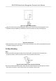

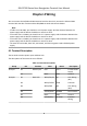
Table Of Contents
- Legal Information
- Symbol Conventions
- Regulatory Information
- Safety Instruction
- Available Models
- Chapter 1 Overview
- Chapter 2 Appearance
- Chapter 3 Installation
- Chapter 4 Wiring
- Chapter 5 Activation
- Chapter 6 Quick Operation
- Chapter 7 Basic Operation
- Chapter 8 Configure the Device via the Mobile Browser
- 8.1 Login
- 8.2 Search Event
- 8.3 User Management
- 8.4 Configuration
- 8.5 Door Operation
- Chapter 9 Select Language
- Chapter 10 Time Settings
- Chapter 11 Environment Settings
- Chapter 12 Privacy Settings
- Chapter 13 Administrator Settings
- Chapter 14 Operation via Web Browser
- 14.1 Login
- 14.2 Forget Password
- 14.3 Live View
- 14.4 Person Management
- 14.5 Search Event
- 14.6 Configuration
- 14.6.1 Set Local Parameters
- 14.6.2 View Device Information
- 14.6.3 Set Time
- 14.6.4 Set DST
- 14.6.5 Change Administrator's Password
- 14.6.6 View Device Arming/Disarming Information
- 14.6.7 Network Settings
- 14.6.8 Set Video and Audio Parameters
- 14.6.9 Set Image Parameters
- 14.6.10 Access Control Settings
- 14.6.11 Card Settings
- 14.6.12 Set Privacy Parameters
- 14.6.13 Time and Attendance Settings
- 14.6.14 Set Biometric Parameters
- 14.6.15 Set Preference
- 14.6.16 Upgrade and Maintenance
- 14.6.17 Device Debugging
- 14.6.18 Log Query
- 14.6.19 Security Mode Settings
- 14.6.20 Certificate Management
- Chapter 15 Client Software Configuration
- 15.1 Configuration Flow of Client Software
- 15.2 Device Management
- 15.3 Group Management
- 15.4 Person Management
- 15.5 Configure Schedule and Template
- 15.6 Set Access Group to Assign Access Authorization to Persons
- 15.7 Configure Advanced Functions
- 15.8 Door Control
- Appendix A. Tips for Scanning Fingerprint
- Appendix B. Tips When Collecting/Comparing Face Picture
- Appendix C. Tips for Installation Environment
- Appendix D. Communication Matrix and Device Command
- Chapter 16 Select Language
- Chapter 17 Time Settings
- Chapter 18 Environment Settings
- Chapter 19 Privacy Settings
- Chapter 20 Administrator Settings

Chapter 4 Wiring
You can connect the NC/NO and COM terminal with the door lock, connect the SEN and GND
terminal with the door contact and the BTN/GND terminal with the exit buon.
Note
●
If c
able size is 18 AWG, you should use a 12 V power supply. And the distance between the
power supply and the device should be no more than 20 m.
●
If the cable size is 15 AWG, you should use a 12 V power supply. And the distance between the
power supply and the device should be no more than 30 m.
●
If the cable size is 12 AWG, you should use a 12 V power supply. And the distance between the
power supply and the device should be no more than 40 m.
●
The external card reader, door lock, exit buon, and door magnec need individual power
supply.
4.1 Terminal
Descripon
The terminals contains power input and door lock.
The descripons of the terminals are as follows:
Table 4-1 Terminal Descripons
Group No. Funcon Color Name Descripon
Group A A1 Power Input Red +12 V 12 VDC Power
Supply
A2 Black GND Ground
Group B B1 Door Lock White/Purple NC Lock Wiring
(NC)
B2 White/Yellow COM Common
B3 White/Red NO Lock Wiring
(NO)
B4 Yellow/Green SENSOR Door Contact
B5 Black GND Ground
B6 Yellow/Grey BUTTON Exit Door
Wiring
DS-K1T320 Series Face Recoginon Terminal User Manual
9