
User's Manual
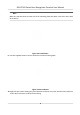
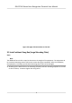
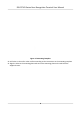
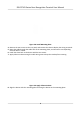
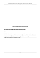
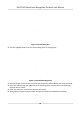
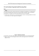
Table Of Contents
- Legal Information
- Symbol Conventions
- Regulatory Information
- Safety Instruction
- Available Models
- Chapter 1 Overview
- Chapter 2 Appearance
- Chapter 3 Installation
- Chapter 4 Wiring
- Chapter 5 Activation
- Chapter 6 Basic Operation
- Chapter 7 Client Software Configuration
- 7.1 Configuration Flow of Client Software
- 7.2 Device Management
- 7.3 Group Management
- 7.4 Person Management
- 7.4.1 Add Organization
- 7.4.2 Configure Basic Information
- 7.4.3 Issue a Card to One Person
- 7.4.4 Upload a Face Photo from Local PC
- 7.4.5 Take a Photo via Client
- 7.4.6 Collect Face via Access Control Device
- 7.4.7 Configure Access Control Information
- 7.4.8 Customize Person Information
- 7.4.9 Configure Resident Information
- 7.4.10 Configure Additional Information
- 7.4.11 Import and Export Person Identify Information
- 7.4.12 Import Person Information
- 7.4.13 Import Person Pictures
- 7.4.14 Export Person Information
- 7.4.15 Export Person Pictures
- 7.4.16 Get Person Information from Access Control Device
- 7.4.17 Move Persons to Another Organization
- 7.4.18 Issue Cards to Persons in Batch
- 7.4.19 Report Card Loss
- 7.4.20 Set Card Issuing Parameters
- 7.5 Configure Schedule and Template
- 7.6 Set Access Group to Assign Access Authorization to Persons
- 7.7 Configure Advanced Functions
- 7.7.1 Configure Device Parameters
- 7.7.2 Configure Remaining Open/Closed
- 7.7.3 Configure Multi-Factor Authentication
- 7.7.4 Configure Custom Wiegand Rule
- 7.7.5 Configure Card Reader Authentication Mode and Schedule
- 7.7.6 Configure First Person In
- 7.7.7 Configure Anti-Passback
- 7.7.8 Configure Device Parameters
- 7.8 Configure Linkage Actions for Access Control
- 7.9 Door Control
- 7.10 Event Center
- 7.11 Time and Attendance
- 7.12 Remote Configuration (Web)
- 7.12.1 View Device Information
- 7.12.2 Change Device Password
- 7.12.3 Time Management
- 7.12.4 System Maintenance
- 7.12.5 Configure RS-485 Parameters
- 7.12.6 Security Mode Settings
- 7.12.7 Network Parameters Settings
- 7.12.8 Report Strategy Settings
- 7.12.9 Network Center Parameters Settings
- 7.12.10 Configure SIP Parameters
- 7.12.11 Set Access Control Parameters
- 7.12.12 Set Face Recognition Terminal Parameters
- 7.12.13 Configure Face Picture Parameters
- 7.12.14 Configure Supplement Light Parameters
- 7.12.15 Set Device No.
- 7.12.16 Configure Video and Audio Parameters
- 7.12.17 Configure Volume Input or Output
- 7.13 Remote Configuration via Client Software
- 7.13.1 Check Device Information
- 7.13.2 Edit Device Name
- 7.13.3 Edit Time
- 7.13.4 Set System Maintenance
- 7.13.5 Manage User
- 7.13.6 Set Security
- 7.13.7 Configure Advanced Network
- 7.13.8 Configure SIP Parameters
- 7.13.9 Configure Face Picture Parameters
- 7.13.10 Configure Supplement Light Parameters
- 7.13.11 Configure Video and Audio Parameters
- 7.13.12 Set Room No.
- 7.13.13 Configure Video and Audio Parameters
- 7.13.14 Configure Volume Input or Output
- Appendix A. Tips for Scanning Fingerprint
- Appendix B. Tips When Collecting/Comparing Face Picture
- Appendix C. Tips for Installation Environment
- Appendix D. Dimension
- Appendix E. Communication Matrix and Device Command

Figure 3-13 Intall Gang Box
2. Use tw
o supplied screws to secure the mounng plate on the gang box.
Figure 3-14 Install Mounng Plate
3. R
emove the two screws on the rear panel and remove the sheet to display the wiring terminals.
4. Route the cable through the cable hole of the mounng plate, and connect to corresponding
external devices' cables.
5. Install the sheet back to the device with the two screws.
6. Apply Silicone sealant among the cable wiring area to keep the raindrop from entering.
DS-K1T341 Series Face
Recognion Terminal User Manual
12