
User's Manual
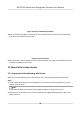
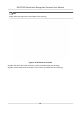
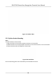
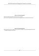
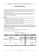
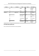
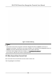
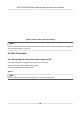

Table Of Contents
- Legal Information
- Symbol Conventions
- Regulatory Information
- Safety Instruction
- Available Models
- Chapter 1 Overview
- Chapter 2 Appearance
- Chapter 3 Installation
- Chapter 4 Wiring
- Chapter 5 Activation
- Chapter 6 Quick Operation
- Chapter 7 Basic Operation
- Chapter 8 Configure the Device via the Mobile Browser
- Chapter 9 Operation via Web Browser
- 9.1 Login
- 9.2 Live View
- 9.3 Person Management
- 9.4 Search Event
- 9.5 Configuration
- 9.5.1 Set Local Parameters
- 9.5.2 View Device Information
- 9.5.3 Set Time
- 9.5.4 Set DST
- 9.5.5 View Open Source Software License
- 9.5.6 Upgrade and Maintenance
- 9.5.7 Log Query
- 9.5.8 Security Mode Settings
- 9.5.9 Certificate Management
- 9.5.10 Change Administrator's Password
- 9.5.11 View Device Arming/Disarming Information
- 9.5.12 Network Settings
- 9.5.13 Set Video and Audio Parameters
- 9.5.14 Customize Audio Content
- 9.5.15 Set Image Parameters
- 9.5.16 Set Supplement Light Brightness
- 9.5.17 Time and Attendance Settings
- 9.5.18 General Settings
- 9.5.19 Video Intercom Settings
- 9.5.20 Access Control Settings
- 9.5.21 Set Biometric Parameters
- 9.5.22 Set Notice Publication
- Chapter 10 Client Software Configuration
- 10.1 Configuration Flow of Client Software
- 10.2 Device Management
- 10.3 Group Management
- 10.4 Person Management
- 10.5 Configure Schedule and Template
- 10.6 Set Access Group to Assign Access Authorization to Persons
- 10.7 Configure Advanced Functions
- 10.8 Door Control
- Appendix A. Tips for Scanning Fingerprint
- Appendix B. Tips When Collecting/Comparing Face Picture
- Appendix C. Tips for Installation Environment
- Appendix D. Dimension
- Appendix E. Communication Matrix and Device Command

Figure 3-14 Secure Mounng Template
3.
Route the cables through the cable hole on the turnsle and x the device into the mounng
plate with 1 SC-KM3×6-T10-SUS screw.
Figure 3-15 Fix the Device
4.
Aer installaon, for the proper use of the device (outdoor use), sck the protecon lm (parts
of models supplied) on the screen.
3.5 Mount With Cylinder Bracket
3.5.1 Preparaon before Mounng with Bracket
Make sure you have drilled holes on the turnsle. If not, follow the steps below to drill holes.
Steps
1.
Use 4 screws (M3 or M4), secured by ange nuts, to install the reinforcing board on the inner
surface of the turnsle.
Note
The distance between the turnsle and the edge should be no longer than 10 mm.
2.
Drill holes on the turnsle's inner surface according to the gure displayed below. And install
water-proof nut.
DS-K1T342 Series Face Recognion Terminal User Manual
16