
User's Manual
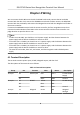
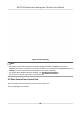
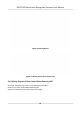
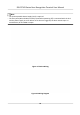
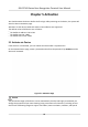
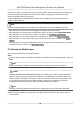
Table Of Contents
- Legal Information
- Symbol Conventions
- Regulatory Information
- Safety Instruction
- Available Models
- Chapter 1 Overview
- Chapter 2 Appearance
- Chapter 3 Installation
- Chapter 4 Wiring
- Chapter 5 Activation
- Chapter 6 Quick Operation
- Chapter 7 Basic Operation
- Chapter 8 Configure the Device via the Mobile Browser
- Chapter 9 Operation via Web Browser
- 9.1 Login
- 9.2 Live View
- 9.3 Person Management
- 9.4 Search Event
- 9.5 Configuration
- 9.5.1 Set Local Parameters
- 9.5.2 View Device Information
- 9.5.3 Set Time
- 9.5.4 Set DST
- 9.5.5 View Open Source Software License
- 9.5.6 Upgrade and Maintenance
- 9.5.7 Log Query
- 9.5.8 Security Mode Settings
- 9.5.9 Certificate Management
- 9.5.10 Change Administrator's Password
- 9.5.11 View Device Arming/Disarming Information
- 9.5.12 Network Settings
- 9.5.13 Set Video and Audio Parameters
- 9.5.14 Customize Audio Content
- 9.5.15 Set Image Parameters
- 9.5.16 Set Supplement Light Brightness
- 9.5.17 Time and Attendance Settings
- 9.5.18 General Settings
- 9.5.19 Video Intercom Settings
- 9.5.20 Access Control Settings
- 9.5.21 Set Biometric Parameters
- 9.5.22 Set Notice Publication
- Chapter 10 Client Software Configuration
- 10.1 Configuration Flow of Client Software
- 10.2 Device Management
- 10.3 Group Management
- 10.4 Person Management
- 10.5 Configure Schedule and Template
- 10.6 Set Access Group to Assign Access Authorization to Persons
- 10.7 Configure Advanced Functions
- 10.8 Door Control
- Appendix A. Tips for Scanning Fingerprint
- Appendix B. Tips When Collecting/Comparing Face Picture
- Appendix C. Tips for Installation Environment
- Appendix D. Dimension
- Appendix E. Communication Matrix and Device Command

Note
●
The Uninterpretable Power Supply (UPS) is required.
●
The re system (NC and COM, normally closed when powering o) is connected with the lock
and the power supply in series. When an re alarm is triggered, the door remains open. In
normal
mes, NC and COM are open.
Figure 4-7 Device Wiring
Figure 4-8 Wiring Diagram
DS-K1T343 Series Face Recognion Terminal User Manual
14