
User's Manual
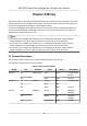
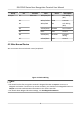
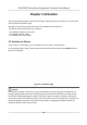
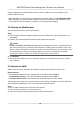
Table Of Contents
- Legal Information
- Symbol Conventions
- Regulatory Information
- Safety Instruction
- Available Models
- Chapter 1 Overview
- Chapter 2 Appearance
- Chapter 3 Installation
- Chapter 4 Wiring
- Chapter 5 Activation
- Chapter 6 Basic Operation
- 6.1 Set Application Mode
- 6.2 Set Administrator
- 6.3 Login
- 6.4 Communication Settings
- 6.5 User Management
- 6.6 Data Management
- 6.7 Identity Authentication
- 6.8 Basic Settings
- 6.9 Set Biometric Parameters
- 6.10 Set Access Control Parameters
- 6.11 Time and Attendance Status Settings
- 6.12 System Maintenance
- 6.13 Two-Way Audio
- Chapter 7 Operation via Web Browser
- 7.1 Login
- 7.2 Live View
- 7.3 Search Event
- 7.4 Configuration
- 7.4.1 View Device Information
- 7.4.2 Set Time
- 7.4.3 Set RS-485 Parameters
- 7.4.4 Set Wiegand Parameters
- 7.4.5 Set DST
- 7.4.6 Upgrade and Maintenance
- 7.4.7 Network Settings
- 7.4.8 Set Video and Audio Parameters
- 7.4.9 Customize Audio Content
- 7.4.10 Set Video Intercom Parameters
- 7.4.11 Set Access Control and Authentication Parameters
- 7.4.12 Set Image Parameters
- 7.4.13 Set Supplement Light Brightness
- 7.4.14 Set Face Parameters
- Chapter 8 Client Software Configuration
- 8.1 Configuration Flow of Client Software
- 8.2 Device Management
- 8.3 Group Management
- 8.4 Person Management
- 8.4.1 Add Organization
- 8.4.2 Configure Basic Information
- 8.4.3 Issue a Card by Local Mode
- 8.4.4 Upload a Face Photo from Local PC
- 8.4.5 Take a Photo via Client
- 8.4.6 Collect Face via Access Control Device
- 8.4.7 Collect Fingerprint via Client
- 8.4.8 Collect Fingerprint via Access Control Device
- 8.4.9 Configure Access Control Information
- 8.4.10 Customize Person Information
- 8.4.11 Configure Resident Information
- 8.4.12 Configure Additional Information
- 8.4.13 Import and Export Person Identify Information
- 8.4.14 Import Person Information
- 8.4.15 Import Person Pictures
- 8.4.16 Export Person Information
- 8.4.17 Export Person Pictures
- 8.4.18 Get Person Information from Access Control Device
- 8.4.19 Move Persons to Another Organization
- 8.4.20 Issue Cards to Persons in Batch
- 8.4.21 Report Card Loss
- 8.4.22 Set Card Issuing Parameters
- 8.5 Configure Schedule and Template
- 8.6 Set Access Group to Assign Access Authorization to Persons
- 8.7 Configure Advanced Functions
- 8.7.1 Configure Device Parameters
- 8.7.2 Configure Remaining Open/Closed
- 8.7.3 Configure Multi-Factor Authentication
- 8.7.4 Configure Custom Wiegand Rule
- 8.7.5 Configure Person Authentication Mode
- 8.7.6 Configure Card Reader Authentication Mode and Schedule
- 8.7.7 Configure First Person In
- 8.7.8 Configure Anti-Passback
- 8.7.9 Configure Device Parameters
- 8.8 Configure Linkage Actions for Access Control
- 8.9 Control Door Status
- 8.10 Event Center
- 8.11 Time and Attendance
- Appendix A. Tips for Scanning Fingerprint
- Appendix B. Tips When Collecting/Comparing Face Picture
- Appendix C. Tips for Installation Environment
- Appendix D. Dimension
- Appendix E. Communication Matrix and Device Command

Chapter 4 Wiring
The device supports connecng to the RS-485 terminal, the door lock, the exit buon, the alarm
output/input devices, the Wiegand card reader, the access controller, and the power supply. You
can wire the peripherals according to the
descripons below.
If connect the Wiegand card reader with the access controller, the face recognion terminal can
transmit the
authencaon informaon to the access controller and the access controller can
judge whether to open the door or not.
Note
• If the cable size is 18 AWG, you should use a 12 V switched-mode power supply. And the
distance between the power supply and the device should be no more than 20 m.
• If the cable size is 15 AWG, you should use a 12 V switched-mode power supply. And the
distance between the power supply and the device should be no more than 30 m.
• If the cable size is 12 AWG, you should use a 12 V switched-mode power supply. And the
distance between the power supply and the device should be no more than 40 m.
4.1 Terminal Descripon
The terminals contains power input, RS-485, Wiegand output, and door lock.
The descripons of the terminals are as follows:
Table 4-1 Terminal
Descripons
Group No. Funcon Color Name Descripon
Group A A1 Power Input Red +12 V 12 VDC Power
Supply
A2 Black GND Ground
Group B B1 RS-485 Yellow 485+ RS-485 Wiring
B2 Blue 485-
B3 Black GND Ground
Group C C1 Wiegand Green W0 Wiegand
Wiring 0
C2 White W1 Wiegand
Wiring 1
C3 White/Black GND Ground
DS-K1T642 Series Face Recognion Terminal User Manual
6