
User's Manual


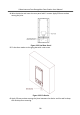


Table Of Contents
- Legal Information
- Symbol Conventions
- Safety Instruction
- Regulatory Information
- 1 Appearance Description
- 2 Terminal and Wiring Description
- 3 Installation
- 4 Activation
- 5 Door Station Local Operation
- 6 Remote Configuration via Web
- 7 Remote Configuration via Client Software
- 8 Batch Configuration Tool
- A. Communication Matrix and Device Command

3.2.3 Flush Mounng with Gang Box
Steps
1. Ca
ve an installaon hole on the wall. Pull out the cable from the wall.
Figure 3-19 Cave Installaon Hole
Note
●
The sug
gested dimension of the installaon hole is 137.75 mm (W) × 335.2 mm
(H) × 40.8 mm (D).
●
The suggested length of the cables le outside is 250 mm.
2. Ins
tall the gang box into the wall.
1) Insert the gang box into the installaon hole. Mark the positon of the gang box
screw holes with a marker, and take out the gang box.
2) Drill 4 screw holes according to the marks on the wall, and insert the expansion
sleeves into the screw holes.
3) Fix the gang box with 4 screws.
Video Intercom Face Recognion Door Staon User Manual
19