
User's Manual
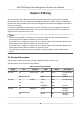

Table Of Contents
- Legal Information
- Symbol Conventions
- Regulatory Information
- Safety Instruction
- Available Models
- Chapter 1 Overview
- Chapter 2 Appearance
- Chapter 3 Installation
- Chapter 4 Wiring
- Chapter 5 Activation
- Chapter 6 Quick Operation
- Chapter 7 Basic Operation
- Chapter 8 Configure the Device via the Mobile Browser
- Chapter 9 Operation via Web Browser
- 9.1 Login
- 9.2 Live View
- 9.3 Person Management
- 9.4 Search Event
- 9.5 Configuration
- 9.5.1 Set Local Parameters
- 9.5.2 View Device Information
- 9.5.3 Set Time
- 9.5.4 Set DST
- 9.5.5 View Open Source Software License
- 9.5.6 Upgrade and Maintenance
- 9.5.7 Log Query
- 9.5.8 Security Mode Settings
- 9.5.9 Certificate Management
- 9.5.10 Change Administrator's Password
- 9.5.11 View Device Arming/Disarming Information
- 9.5.12 Network Settings
- 9.5.13 Set Video and Audio Parameters
- 9.5.14 Customize Audio Content
- 9.5.15 Set Image Parameters
- 9.5.16 Set Supplement Light Brightness
- 9.5.17 Time and Attendance Settings
- 9.5.18 General Settings
- 9.5.19 Video Intercom Settings
- 9.5.20 Access Control Settings
- 9.5.21 Set Biometric Parameters
- 9.5.22 Set Notice Publication
- Chapter 10 Client Software Configuration
- 10.1 Configuration Flow of Client Software
- 10.2 Device Management
- 10.3 Group Management
- 10.4 Person Management
- 10.5 Configure Schedule and Template
- 10.6 Set Access Group to Assign Access Authorization to Persons
- 10.7 Configure Advanced Functions
- 10.8 Door Control
- Appendix A. Tips for Scanning Fingerprint
- Appendix B. Tips When Collecting/Comparing Face Picture
- Appendix C. Tips for Installation Environment
- Appendix D. Dimension
- Appendix E. Communication Matrix and Device Command

Chapter 4 Wiring
You can connect the RS-485 terminal with the RS-485 card reader, connect the NC and COM
terminal with the door lock, connect the SENSOR terminal with the door contact, the BTN/GND
terminal with the exit
buon, and connect the Wiegand terminal with the Wiegand card reader or
the access controller.
If connect the WIEGAND terminal with the access controller, the face
recognion terminal can
transmit the authencaon informaon to the access controller and the access controller can
judge whether to open the door or not.
Note
●
If cable size is 18 AWG, you should use a 12 V power supply. And the distance between the
power supply and the device should be no more than 20 m.
●
If the cable size is 15 AWG, you should use a 12 V power supply. And the distance between the
power supply and the device should be no more than 30 m.
●
If the cable size is 12 AWG, you should use a 12 V power supply. And the distance between the
power supply and the device should be no more than 40 m.
●
The external card reader, door lock, exit buon, and door magnec need individual power
supply.
4.1 Terminal Descripon
The terminals contains power input, RS-485, Wiegand output, and door lock.
The descripons of the terminals are as follows:
Table 4-1 Terminal
Descripons
Group No. Funcon Color Name Descripon
Group A A1 Power Input Red +12 V 12 VDC Power
Supply
A2 Black GND Ground
Group B B1 RS-485 Yellow 485+ RS-485 Wiring
B2 Blue 485-
B3 Red/Black GND Ground
Group C C1 Wiegand Green W0 Wiegand
Wiring 0
C2 White W1 Wiegand
Wiring 1
DS-K1T343 Series Face Recognion Terminal User Manual
8