Video Intercom Module Door Station User Manual
Video Intercom Module Door Station User Manual Legal Information ©2021 Hangzhou Hikvision Digital Technology Co., Ltd. All rights reserved. About this Manual The Manual includes instructions for using and managing the Product. Pictures, charts, images and all other information hereinafter are for description and explanation only. The information contained in the Manual is subject to change, without notice, due to firmware updates or other reasons.
Video Intercom Module Door Station User Manual CONNECTION WITH THE USE OF THE PRODUCT, EVEN IF HIKVISION HAS BEEN ADVISED OF THE POSSIBILITY OF SUCH DAMAGES OR LOSS.
Video Intercom Module Door Station User Manual Symbol Conventions The symbols that may be found in this document are defined as follows. Symbol Danger Caution Note Description Indicates a hazardous situation which, if not avoided, will or could result in death or serious injury. Indicates a potentially hazardous situation which, if not avoided, could result in equipment damage, data loss, performance degradation, or unexpected results.
Video Intercom Module Door Station User Manual Regulatory Information FCC Information Please take attention that changes or modification not expressly approved by the party responsible for compliance could void the user's authority to operate the equipment. FCC compliance: This equipment has been tested and found to comply with the limits for a Class B digital device, pursuant to part 15 of the FCC Rules.
Video Intercom Module Door Station User Manual EU Conformity Statement This product and - if applicable - the supplied accessories too are marked with "CE" and comply therefore with the applicable harmonized European standards listed under the EMC Directive 2014/30/EU, the RoHS Directive 2011/65/EU 2012/19/EU (WEEE directive): Products marked with this symbol cannot be disposed of as unsorted municipal waste in the European Union.
Video Intercom Module Door Station User Manual Contents 1 Appearance ................................................................................................ 1 2 Terminal and Wiring ................................................................................... 8 2.1 Terminal Description ......................................................................................... 8 2.2 Module Door Station Wiring ........................................................................... 12 2.2.
Video Intercom Module Door Station User Manual 4 Activation ................................................................................................. 54 4.1 Activate Device via Client Software ................................................................. 54 4.2 Edit Network Parameters ................................................................................ 54 5 Configuration via Client Software ............................................................. 56 5.1 Device Management .....
Video Intercom Module Door Station User Manual 5.5.1 Add Person ............................................................................................. 85 5.5.2 Modify and Delete Person ...................................................................... 87 5.5.3 Import and Export Person Information .................................................. 87 5.5.4 Get Person Information from Device ...................................................... 88 5.5.5 Change Person to Other Organization ........
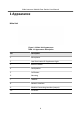
Video Intercom Module Door Station User Manual 1 Appearance Main Unit Figure 1-1 Main Unit Appearance Table 1-1 Appearance Description No.
Video Intercom Module Door Station User Manual Note • Nametag area supports insert customized name card. The suggested card size is: 58 (L) x 11.7(W) mm. • The module connecting interface is used to connect other function module, such as nametag module, keypad module, card reader module, etc. All these modules are known as sub module. Two-Wire Main Unit Figure 1-2 Two-Wire Main Unit Table 1-2 Appearance Description No.
Video Intercom Module Door Station User Manual Note • Nametag area supports insert customized name card. The suggested card size is: 58 (L) x 11.7(W) mm. • The module connecting interface is used to connect other function module, such as nametag module, keypad module, card reader module, etc. All these modules are known as sub module. Nametag Module Figure 1-3 Nametag Module Appearance Table 1-3 Appearance Description No.
Video Intercom Module Door Station User Manual Keypad Module Figure 1-4 Keypad Module Appearance Table 1-4 Appearance Description No.
Video Intercom Module Door Station User Manual Table 1-5 Appearance Description No. Description 1 Calling Indicator 2 Two-way Audio Indicator 3 Unlock Indicator 4 Module-connecting Interface (output) 5 Module-connecting Interface(input) 6 Debugging Port Card Reader Module Figure 1-6 Card Reader Module Table 1-6 Appearance Description No.
Video Intercom Module Door Station User Manual Display Module Figure 1-7 Display Module Table 1-7 Description No. Description No.
Video Intercom Module Door Station User Manual Table 1-8 Description No. Description 1 Display Area 2 Module-connecting Interface (output) 3 Module-connecting Interface (input) 4 Debugging Port Touch-Display Module Figure 1-9 Touch-Display Module Table 1-9 Description No.
Video Intercom Module Door Station User Manual 2 Terminal and Wiring 2.1 Terminal Description Main Unit Terminals Figure 2-1 Main Unit Terminals Table 2-1 Descriptions of Terminals and Interfaces No.
Video Intercom Module Door Station User Manual No. Interface Description B4 AIN4 For the access of Exit Button 2 B5 485- Module-connecting Interface B6 485+ B7 12 V OUT B8 GND C LAN PoE Network Interface(Supports IEEE 802.3af/at-Compliant Devices) Two-Wire Main Unit Terminal Figure 2-2 Two-Wire Main Unit Terminal Table 2-2 Descriptions of Terminals and Interfaces No.
Video Intercom Module Door Station User Manual No.
Video Intercom Module Door Station User Manual No. Interface Description B1 485- Module-Connecting Interface (Output) B2 485+ B3 12V OUT B4 GND Touch-Display Module Figure 2-4 Touch-Display Module Table 2-4 Description No.
Video Intercom Module Door Station User Manual No. Interface Description C2 CVSB IN Composite Video Broadcast Signal Input (Reserved) C3 LINEOUT- Audio Output (Reserved) C4 LINEOUT+ 2.2 Module Door Station Wiring 2.2.1 Door Lock Wiring Figure 2-5 Door Lock Wiring Note Terminal NC1/COM is set as default for accessing magnetic lock/electric bolt; terminal NO2/COM is set as default for accessing electric strike. 2.2.
Video Intercom Module Door Station User Manual Figure 2-6 Door Contact Wiring Note AIN1 and AIN2 are defaulted to connect door contact. Door contact connected to AIN1 detects status of the lock that connected to NC1/NO1; Door contact connected to AIN2 detects the status of the lock connected to NC2/NO2. 2.2.
Video Intercom Module Door Station User Manual Note AIN3 and AIN4 are set as default for connecting exit button. Exit button connected to AIN3 opens the lock connected to NC1/NO1; Exit button connected to AIN4 controls the lock that connected to NC2/NO2. 2.2.4 RS-485 Card Reader Wiring To connect RS-485 card reader, refer to the picture below.
Video Intercom Module Door Station User Manual 3 Installation Note • Make sure the device in the package is in good condition and all the assembly parts are included. • Sub module must work along with the main unit. • Set the sub module address before start the installation steps. • Make sure the place for surface mounting is flat. • Make sure all the related equipment is power-off during the installation.
Video Intercom Module Door Station User Manual Note • Bit 1, 2, 3, 4 are used to coding the sub module address. Bit 5, 6, 7 are reserved. Set Bit 8 as on to enable a resistance (120Ω). • Valid sub module address is from 1 to 8. The address should be unique for connecting to the main unit. The sub module address and its corresponding switch status are displayed as below.
Video Intercom Module Door Station User Manual Before You Start Figure 3-2 Mounting Frame Note • The dimension of one module mounting frame (W × H × D) is: 117 mm × 107 mm × 32.7 mm. • The dimensions above are for reference only. The actual size can be slightly different from the theoretical dimension. Steps 1. Paste the installation Sticker 1 onto the wall. Make sure the sticker is placed horizontally via measuring with the gradienter. 2. Drill 4 holes according to the screw holes on the sticker.
Video Intercom Module Door Station User Manual Figure 3-3 Drill Screw Holes 3. Remove the stricker and insert the expansion sleeves into the screw holes. 4. Fix the mounting frame onto the wall with 4 expansion bolts.
Video Intercom Module Door Station User Manual 5. Connect the cables to the corresponding interfaces of the main unit and insert the main unit into the frame. Figure 3-5 Insert the Main Unit 6. Fix the cover onto the frame. Figure 3-6 Fix the Cover 3.2.
Video Intercom Module Door Station User Manual Before You Start Figure 3-7 Front and Side View of the Gang Box Figure 3-8 Gang Box Note The dimension of one-module gang box is: 115 (W) × 134 (H) × 56 (D) mm. The dimension is for reference only.
Video Intercom Module Door Station User Manual Steps 1. Drill an installation hole, and pull the cables out. Note • The suggested dimension of installation hole is 118 (W) × 108 (H) × 45.5 (D) mm. • The suggested length of cables left outside is 100 mm. Figure 3-9 Drill Installation Hole 2. Remove the plastic sheet of the cable entry. 3. Mark the gang box screw holes on the wall. 1) Route the cables through the gang box hole. 2) Insert the gang box into the installation hole.
Video Intercom Module Door Station User Manual 4. Drill 4 holes according to marks on the wall, and insert the expansion sleeves into the screw holes. Note The suggested size of the hole is 6 (diameter) × 45 (depth) mm. 5. Route the cables through the gang box hole. Insert the gang box into the installation hole. Fix the gang box with 4 expansion bolts. Figure 3-11 Fix the Gang Box 6. Fill the gap between the gang box and the wall with concrete. Remove the 4 mounting ears with tool after concrete is dry.
Video Intercom Module Door Station User Manual 7. Connect the cables to the corresponding interfaces of the main unit and insert the unit into the gang box. Figure 3-13 Insert the Main Unit 8. Fix the cover and the main unit with 2 socket head cap screws by using a hexagon wrench (supplied). Figure 3-14 Fix the Cover 3.3 Two-Module Installation 3.3.
Video Intercom Module Door Station User Manual Before You Start Figure 3-15 Mounting Frame Note • The dimension of two-module mounting frame (W × H × D) is: 219 mm × 107 mm × 32.7 mm. • The dimensions above are for reference only. The actual size can be slightly different from the theoretical dimension. Steps 1. Paste the installation Sticker 1 onto the wall. Make sure the sticker is placed horizontally via measuring with the gradienter. 2. Drill 4 holes according to the screw holes on the sticker.
Video Intercom Module Door Station User Manual Figure 3-16 Drill Screw Holes 3. Remove the sticker and insert the expansion sleeves into the screw holes. 4. Fix the mounting frame onto the wall with 4 expansion bolts. Figure 3-17 Fix the Mounting Frame 5. Thread the module-connecting line across the thread hole of the frame. Pass the main unit connecting lines across the thread hole to the upper grid.
Video Intercom Module Door Station User Manual Figure 3-18 Placement of Lines 6. Connect the cables. 1) Connect the lines and module-connecting line to the corresponding interfaces of the main unit, then place the main unit into the upper grid. 2) Connect the other end of the module-connecting line to the input interface of the sub module. 3) Organize the cable with cable tie in the package. The suggested cable connection picture as shown below.
Video Intercom Module Door Station User Manual Figure 3-19 Line Connection Effect Picture 7. Insert the modules into the frame after wiring. The main unit must be placed in the top grid. Figure 3-20 Insert the Modules 8. Use the hexagon wrench in the package to fix the cover onto the frame.
Video Intercom Module Door Station User Manual Figure 3-21 Fix the Cover 3.3.
Video Intercom Module Door Station User Manual Note The dimension of two-module gang box is: 237 (W) × 134 (H) × 56 (D) mm. The dimension is for reference only. Steps 1. Drill the installation hole, and pull the cable out. Note • The suggested dimension of installation hole is 220 (W) × 108 (H) × 45.5 (D) mm. • The suggested length of cables left outside is 270 mm. Figure 3-23 Drill the Installation Hole 2. Select a cable entry and remove the plastic sheet. 3. Mark the gang box screw holes on the hole.
Video Intercom Module Door Station User Manual Figure 3-24 Mark the Screw Holes 4. Drill 4 holes according to the marks on the wall, and insert the expansion sleeves into the screw holes. The suggested size of hole is 6 (diameter) × 45 (depth) mm. 5. Fix the gang box with 4 expansion bolts. Figure 3-25 Fix the Gang Box 6. Fill the gap between the gang box and the wall with concrete. Remove the mounting ears with tool after concrete is dry.
Video Intercom Module Door Station User Manual Figure 3-26 Remove the Mounting Ears 7. Connect cables and insert the modules. 1) Connect Cable 1 and one end of Cable 2 to the corresponding interfaces of the main unit, then insert the main unit into the upper grid. 2) Connect the other end of Cable 2 to the input interface of the sub module. Insert it into the lower grid.
Video Intercom Module Door Station User Manual Note Cable 1 refers to the cables pulled out from the wall that connected to the main unit. Cable 2 refers to the module-connecting line in the accessory package. 8. Fix the cover with 2 socket head cap screws by using a hexagon wrench (supplied). Figure 3-28 Fix the Cover 3.4 Three-Module Installation 3.4.
Video Intercom Module Door Station User Manual Note • The dimension of two-module mounting frame (W × H × D) is: 320.8 mm × 107 mm × 32.7 mm. • The dimensions above are for reference only. The actual size can be slightly different from the theoretical dimension. Steps 1. Paste the installation sticker 1 onto the wall. Make sure the sticker is placed horizontally via measuring with the gradienter. 2. Drill 4 holes according to the screw holes on the sticker.
Video Intercom Module Door Station User Manual Figure 3-31 Fix the Mounting Frame Note The mounting frame should be placed exactly as shown below for this step. The tamper plate should be at the low right of the first grid. Figure 3-32 Mounting Frame 5. Thread the module-connecting line across the thread holes of the frame. Pass the main unit connecting line across the thread hole to the top grid.
Video Intercom Module Door Station User Manual Figure 3-33 Placement of Lines 6. Connect the cables. 1) Connect the lines and module-connecting line 1 to the corresponding interfaces of the main unit, then place the main unit into the upper grid. 2) Connect the other end of the module-connecting line 1 to the input interface of the sub module. Connect two sub modules via module-connecting line 2. 3) Organize the cables with cable tie in the package. The suggested cable connection picture as shown below.
Video Intercom Module Door Station User Manual Figure 3-35 Insert the Modules into the Frame 8. Use the hexagon wrench in the package to fix the cover onto the frame. Figure 3-36 Fix the Cover 3.4.
Video Intercom Module Door Station User Manual Before You Start Figure 3-37 Gang Box Note • The dimension of one-module gang box is: 338.8(W)×134(H)×56(D) mm. • The dimensions above are for reference only. The actual size can be slightly different from the theoretical dimension. Steps 1. Cave the installation hole, and pull the cable out.The suggested dimension of installation hole is 321.8(W)×108(H)×45.5(D) mm. The suggested length of cables left outside is 270 mm.
Video Intercom Module Door Station User Manual Figure 3-38 Cave the Installation Hole 2. Select a cable entry and remove the plastic sheet. 3. Mark the gang box screw holes on the wall. 1) Route the cables through the gang box hole. 2) Insert the gang box into the installation hole. 3) Mark the gang box screw holes' position with a marker, and take out the gang box. Figure 3-39 Mark the Screw Holes 4. Drill 4 holes according to marks on the wall, and insert the expansion sleeves into the screw holes.
Video Intercom Module Door Station User Manual Figure 3-40 Fix the Gang Box 6. Fill the gap between the gang box and wall with concrete. Remove the mounting ears with tool after concrete is dry. Figure 3-41 Remove the Mounting Ears 7. Connect cables and insert the modules. 1) Connect Cable 1 and one end of Cable 2 to the corresponding interfaces of the main unit, then insert the main unit into the upper grid. 2) Connect the other end of Cable 2 to the input interface of Sub Module 1.
Video Intercom Module Door Station User Manual Figure 3-42 Connect Cables and Insert Modules Note Cable 1 refers to the cables pulled out from the wall that connected to the main unit. Cable 2 and Cable 3 refer to the module-connecting line in the accessory package. 8. Fix the cover and the main unit with 2 socket head cap screws by using a hexagon wrench (supplied). Figure 3-43 Fix the Cover 3.5 More-Than-Three Module Installation 3.5.
Video Intercom Module Door Station User Manual Before You Start Figure 3-44 Mounting Frame Note • It takes two three-module mounting frames. The dimension of three-module mounting frame (W × H × D) is: 320.8 mm × 107 mm × 32.7 mm. • The dimensions above are for reference only. The actual size can be slightly different from the theoretical dimension. Steps 1. Paste two Sticker 1 onto the wall. Make sure the stickers are placed horizontally via measuring with the gradienter. 2.
Video Intercom Module Door Station User Manual Figure 3-45 Drill Screw Holes 4. Remove the stickers and insert the expansion sleeves into the screw holes. 5. Thread the module-connecting line (400 mm) and grounding line across the thread hole of both frames.
Video Intercom Module Door Station User Manual Note • There are 6 module-connecting lines in the package: 190 mm × 4 and 400 mm × 2. • Take the 400 mm module-connecting line for this step. • The green-yellow line in the package is for grounding. 6. Fix the mounting frame onto the wall with 8 expansion bolts. Figure 3-47 Fix the Mounting Frame 7. Pass the main unit connecting line across the thread hole to the top grid of the left frame.
Video Intercom Module Door Station User Manual 1) Connect the cables from the wall and module-connecting line 1 to the corresponding interfaces of the main unit, then place the main unit into the upper grid. 2) Connect the other end of the module-connecting line 1 to the input interface of the sub module. Connect all sub modules via module-connecting lines. 3) Organize the cable with cable tie in the package. The suggested cable connection picture as shown below.
Video Intercom Module Door Station User Manual Figure 3-50 Insert the Modules 10. Pull the grounding line out and fixed its two end to the screw on the cover. Figure 3-51 Connect the Grounding Line to the Cover 11. Use the hexagon wrench in the package to fix the cover onto the frame.
Video Intercom Module Door Station User Manual Figure 3-52 Fix the Cover 3.5.
Video Intercom Module Door Station User Manual Before You Start Figure 3-53 Gang Box Note It takes two three-module gang boxes. The dimension of the gang box is: 338.8 (W) × 134 (H) × 56 (D) mm. The dimension is for reference only.
Video Intercom Module Door Station User Manual Steps 1. Drill the installation hole, and pull the cable out.The suggested dimension of installation hole is 321.8 (W) × 315 (H) × 45.5 (D) mm. The suggested length of cables left outside is 270 mm. Figure 3-54 Cave the Installation Hole 2. Connect two gang boxes as below. Figure 3-55 Connect Two Gang Boxes 3. Select a cable entry and remove the plastic sheet.
Video Intercom Module Door Station User Manual 4. Remove the plastic sheets on the side of the gang boxes (shown as 1 and 2) below: Figure 3-56 Remove the Plastic Sheets 5. Mark the gang box screw holes on the wall. 1) Route the cables through the gang box hole. 2) Insert the gang box into the installation hole. 3) Mark the gang box screw holes' position with a marker, and take out the gang box.
Video Intercom Module Door Station User Manual 6. Drill 8 holes according to the marks on the wall, and insert the expansion sleeves into the screw holes. The suggested size of hole is 6 (diameter) × 45 (depth) mm. 7. Fix the gang boxes with 8 expansion bolts. Figure 3-58 Fix the Gang Boxes 8. Fill the gap between the gang box and wall with concrete. Remove the mounting ears with tool after concrete is dry. Route the grounding line through the cable entries.
Video Intercom Module Door Station User Manual 1) Connect Cable 1 and one end of Cable 2 to the corresponding interfaces of the Main Unit, then place the Main Unit into the upper grid of the left gang box. 2) Connect the other end of Cable 2 to the input interface of Sub Module 1. Connect one end of Cable 3 to the output interface of Sub Module 1 and insert it into the middle grid of the left gang box. 3) Finish the wiring and inserting according to the cable number and the position shown as below.
Video Intercom Module Door Station User Manual Note • Cable 2,3,5 and 6 are the module-connecting lines (190 mm) in the package. • Cable 4 is the module-connecting line (400 mm) in the package. • Main unit must be put in the top grid. 10. Pull the grounding line out and fixed its two end to the screw on the cover. Figure 3-62 Connect the Grounding Line to the Cover 11. Fix the cover with 2 socket head cap screws by using a hexagon wrench (supplied).
Video Intercom Module Door Station User Manual Figure 3-63 Fix the Cover 53
Video Intercom Module Door Station User Manual 4 Activation 4.1 Activate Device via Client Software You can only configure and operate the door station after creating a password for the device activation. Default parameters of door station are as follows: • Default IP Address: 192.0.0.65. • Default Port No.: 8000. • Default User Name: admin. Steps 1. Run the client software, click Maintenance and Management → Device Management → Device to enter the page. 2. Click Online Device. 3.
Video Intercom Module Door Station User Manual To operate and configure the device via LAN (Local Area Network), you need connect the device in the same subnet with your PC. You can edit network parameters via iVMS-4200 client software. Steps 1. Select an online activated device and click the Modify Netinfo. 2. Edit the device IP address and gateway address to the same subnet with your computer. 3. Enter the password and click OK to save the network parameters modification. Note • The default port No.
Video Intercom Module Door Station User Manual 5 Configuration via Client Software 5.1 Device Management Device management includes device activation, adding device, editing device, and deleting device, and so on. After running the iVMS-4200, video intercom devices should be added to the client software for remote configuration and management. 5.1.1 Add Online Device Before You Start Make sure the device to be added is in the same subnet with your computer. Otherwise, please edit network parameters first.
Video Intercom Module Door Station User Manual Figure 5-1 Add to the Client 5.1.2 Add Device by IP Address Steps 1. Click +Add to pop up the adding devices dialog box. 2. Select IP/Domain as Adding Mode. 3. Enter corresponding information. 4. Click Add. 5.1.
Video Intercom Module Door Station User Manual You can add many devices at once whose IP addresses are among the IP segment. Steps 1. Click +Add to pop up the dialog box. 2. Select IP Segment as Adding Mode. 3. Enter corresponding information, and click Add. 5.2 Live View via Door Station Steps 1. On the main page of the client software, click Main View to enter the Live View page. 2. In the left list of the window, double-click the device IP or click the play icon to live view. 3.
Video Intercom Module Door Station User Manual Figure 5-2 Device Management Add Device • Click Add to add the indoor station or sub door station. Enter the parameters and click OK to add. • Click Import. Enter the information of the device in the template to import devices in batch. Export Click Export to export the information to the PC. Delete Select the device and click Delete to remove the selected device from the list.
Video Intercom Module Door Station User Manual Upgrade Manually Click Upload Upgrading Package to import the upgrading package. Click Upgrade Now to start upgrading. View Version Put the mouse on the Upgrading button to view the upgrading version and time. Optional: Set Device Information. • Click to edit device information. • Click to delete device information from the list. • Select Status and Device Type to search devices. 5.3.
Video Intercom Module Door Station User Manual Set the stream type as Main Stream or Sub-stream. Play Performance Set the live view performance to Shortest Delay, Balanced or Fluent. Auto Start Live View Check Yes to enable the function. Image Format Select the image format for picture capture. Click Save to enable the settings. Record File Parameters Record File Size Select the packed size of the manually recorded and downloaded video files to 256M, 512M or 1G.
Video Intercom Module Door Station User Manual Basic Information Click System Settings → Basic Information to enter the settings page. On the page, you can edit Device Name and Device No. Set the Language and System Type according to your needs. Click Save to enable the settings. Time Settings Click System Settings → Time Settings to enter the settings page. Select the Time Zone of your location from the drop-down list. • Enable NTP, set the Server Address, NTP Port and Interval. • Enable Manual Time Sync.
Video Intercom Module Door Station User Manual Figure 5-4 Maintenance • Reboot: Click Reboot to reboot the device. • Default Click Default to restore all parameters to default settings. Restore All Click Restore All to reset all the parameters, except the IP parameters and user information, to the default settings. • Export parameters: 1. Select Device Parameters, and click Export to pop up the dialog box. 2. Set and confirm the encryption password. 3. Click OK to export parameters. • Import Config.
Video Intercom Module Door Station User Manual Authentication Click Security → Authentication to enter the settings page. On the page, you can select RTSP Authenticationaccording to your actual needs. Click Save to enable the settings. Security Service Click Security → Security Service to enter the settings page. On the page, you can enable SSH according to your actual needs. Click Save to enable the settings. User Management Click User Management to enter the settings page.
Video Intercom Module Door Station User Manual Arming/Disarming Information Click User Management → Arming/Disarming Information to view the information. Click Refresh to get the present information. 5.3.4 Network Settings TCP/IP Settings TCP/IP settings must be properly configured before you operate the device over network. The device supports IPv4. Steps 1. Click Network → Basic Settings → TCP/IP to enter the settings page. Figure 5-6 TCP/IP Settings 2. Configure the network parameters.
Video Intercom Module Door Station User Manual - Set the IPv4 Address, IPv4 Subnet Mask and IPv4 Default Gateway manually. 3. Configure the corresponding DNS server parameters. 4. Click Save to enable the settings. Port Settings Steps 1. Click Network → Basic Settings → Port to enter the settings page. Figure 5-7 Port Settings 2. Set the ports of the device. HTTP Port The default port number is 80, and it can be changed to any port No. which is not occupied.
Video Intercom Module Door Station User Manual Steps 1. Click Network → Basic Settings → SIP to enter the settings page. Figure 5-8 SIP Settings 2. Check Enable VOIP Gateway. 3. Configure the SIP parameters. 4. Click Save to enable the settings. FTP Settings Steps 1. Click Network → Advanced → FTP to enter the settings page.
Video Intercom Module Door Station User Manual Figure 5-9 FTP Settings 2. Check Enable FTP. 3. Select Server Type. 4. Input the Server IP Address and Port. 5. Configure the FTP Settings, and the user name and password are required for the server login. 6. Set the Directory Structure, Parent Directory and Child Directory. 7. Set the picture naming rules. 8. Click Save to enable the settings.
Video Intercom Module Door Station User Manual 5.3.5 Video & Audio Settings Video Parameters Steps 1. Click Video/Audio → Video to enter the settings page. Figure 5-10 Video Parameters 2. Select the Stream Type. 3. Configure the video parameters. Stream Type Select the stream type to main stream or sub stream. Video Type Select the stream type to video stream, or video & audio composite stream. The audio signal will be recorded only when the Video Type is Video & Audio.
Video Intercom Module Door Station User Manual When bitrate type is selected as Variable, 6 levels of video quality are selectable. Frame Rate Set the frame rate. The frame rate is to describe the frequency at which the video stream is updated and it is measured by frames per second (fps). A higher frame rate is advantageous when there is movement in the video stream, as it maintains image quality throughout. Max. Bitrate Set the max. bitrate from 32 to 16384 Kbps.
Video Intercom Module Door Station User Manual 3. Adjust the Input Volume, Output Volume and Speak Volume. Note Available range of volume: 0 to 10. 4. Click Save to save the settings. 5.3.6 Image Settings Display Settings Configure the image adjustment, backlight settings and other parameters in display settings. Steps 1. Click Image → Display Settings to enter the display settings page. Figure 5-12 Display Settings 2. Select the Format. 3. Set the display parameters.
Video Intercom Module Door Station User Manual Saturation Saturation describes the colorfulness of the image color, which ranges from 1 to 100. Sharpness Sharpness describes the edge contrast of the image, which ranges from 1 to 100. 4. Set the Day/Night Mode. - Figure 5-13 Day/Night Mode Set Day Mode or Night Mode manually. Set the mode as Auto and edit the sensitivity according to your needs. Set the mode as Scheduled-Switch. Set the start time and end time.
Video Intercom Module Door Station User Manual 1) Check the checkbox to enable BLC. 2) Select BLC Area. 6. Click Save to enable the settings. OSD Settings You can customize the camera name, time/date format, display mode, and OSD size displayed on the live view. Steps 1. Click Image → OSD Settings to enter the settings page. 2. Check the corresponding checkbox to select the display of camera name, date or week if required. 3. Edit the Camera Name. 4.
Video Intercom Module Door Station User Manual You can create call schedule, or else the device will call indoor station all day by default. Steps 1. Click Schedule → Video Intercom → Call Schedule . 2. Click the next row below Enable Indoor Station All Day by Default. 3. Enter Schedule Name. 4. Select Call Type. 5. Set Weekly Schedule. 1) Click Weekly Schedule. Figure 5-15 Weekly Schedule 2) Drag mouse to set the schedule according to the actual needs.
Video Intercom Module Door Station User Manual Figure 5-16 Holiday Schedule 2) Click Add. 3) Set Start Time and End Time. 4) Select Call Type. 5) Drag mouse to set the schedule according to the actual needs. 6) Click OK. 7) You can edit or delete the schedule according to the actual needs. 8) Click Save. Note The holiday schedule have higher priority than weekly schedule when you set the two schedule at the same time. 5.3.8 Intercom Settings Device No. Settings Steps 1. Click Device No. to enter the page.
Video Intercom Module Door Station User Manual Figure 5-17 Device No. Settings 2. Select the device type from the drop-down list, and set the corresponding information including Building No., Floor No., Door Station No., Community No. and Unit No. Note When you select Outer Door Station as Device Type, only Outer Door Station No. and Community No. can be set. 3. Click Save to enable the device number configuration. Note • For main door station (D series or V series), the No. is 0.
Video Intercom Module Door Station User Manual 3. Set Main Station IP and VideoIntercom Server IP. 4. Enable Protocol 1.0. 5. Click Save to enable the settings. Time Parameters Go to Intercom → Time Parameters to enter the page. Configure Max. Call Duration, Max. Message Duration, Max. Ring Duration, and click Save. Note • Max. call duration between the module indoor station and client ranges from 90 s to 120 s.
Video Intercom Module Door Station User Manual Figure 5-18 Press Button to Call 2. Edit room No. in the button settings and select Link Time Schedule. Note • The number of buttons may vary with different models. Please refer to the actual product. • The schedule settings refers to Schedule Settings for details. 3. Click Save to enable the settings. Input and Output Go to Intercom → I/O Settings to enter the settings page. Figure 5-19 IO Input and Output Select I/O Input No., Input, I/O Output No.
Video Intercom Module Door Station User Manual Table 5-1 I/O Input • I/O Input No. Input 1 Door Status 2 Disable/Door Status 3 Exit Button 4 Disable/Exit Button I/O Output supports 2-channel outputs. Table 5-2 I/O Output I/O Output No. Output 1 Electric Lock 2 Disable/Electric Lock Sub Module Configuration Steps 1. Click Intercom → Sub Module Configuration , and you can view the sub module information, including No., module type, status, and version. 2. Click to edit the sub module.
Video Intercom Module Door Station User Manual Note • The module address is used to differentiate the sub modules. See Configure Sub Module Address for detailed configuration instructions. • For the other sub modules (indicator module, keypad module and card reader module), it prompts Not supported. • The room No. for the main unit's call button is 1 by default; and the room No. for the nametag modules call buttons are 2 to 7 by default. Number Settings Steps 1.
Video Intercom Module Door Station User Manual Figure 5-20 Password Settings 2. Select Password Type. 3. Enter and confirm the password. 4. Click Save to enable the settings. Door Parameters Steps 1. Click Access Control → Door Parameters to enter the settings page. Figure 5-21 Door Parameters 2. Select the door and edit the door name. 3. Edit Open Duration.
Video Intercom Module Door Station User Manual 4. Set door contact status. 5. Click Save to enable the settings. Card Security Click Access Control → Card Security to enter the settings page. Slide to enable card encryption parameters. Click Save to enable the settings. Elevator Control Before You Start Make sure that the door station is in the mode of main door station. Only the main door station supports elevator control function. Steps 1.
Video Intercom Module Door Station User Manual Figure 5-22 Elevator Control 2. Check to enable elevator control function. 3. Select an Elevator No., and select an elevator controller type for the elevator. 4. Select Interface Type. 5. Enter Negative Floor Capacity, and select Alarm Receiver Type. 6. Enter the elevator controller's Server IP Address, Port No., User Name, and Password. 7. Click Save to enable the settings. Note • Up to 4 elevator controllers can be connected to one door station.
Video Intercom Module Door Station User Manual 5.3.10 Theme Settings Set the advertisement on the main page of the device. Steps 1. Click Configuration → Theme to enter the settings page. 2. Check to enable screen saving function. 3. Set the advertisement theme. 1) Click + Add Theme. 2) Create a theme name, and select the advertisement body as picture or Video. 3) Click Save. 4. Click + to select a picture from the local as the material to be played in standby, and click upload. 5. Set the play schedule.
Video Intercom Module Door Station User Manual Steps 1. In the organization list on the left, click +Add. 2. Enter the Organization Name as desired. 3. Click OK to save the adding. 4. Optional: You can add multiple levels of organizations according to the actual needs. 1) You can add multiple levels of organizations according to the actual needs. 2) Then the added organization will be the sub-organization of the upper-level organization. Note Up to 10 levels of organizations can be created. 5.4.
Video Intercom Module Door Station User Manual Person information is necessary for the video intercom system. And when you set linked device for the person, the intercom between intercom devices can be realized. Steps 1. Select an organization in the organization list and click Add on the Person panel to pop up the adding person dialog. Note The Person No. will be generated automatically and is editable. 2. Set basic person information.
Video Intercom Module Door Station User Manual Note If you select Analog Indoor Station in the Linked Device, the Door Station field will display and you are required to select the door station to communicate with the analog indoor station. Room No. You can enter the room No. of the person. 2) Click OK to save the settings. 5. Click Add to save the settings. 5.5.2 Modify and Delete Person Select the person and click Edit to open the editing person dialog.
Video Intercom Module Door Station User Manual 4) Click ... to select the Excel file with person information. 5) Click OK to start importing. 5.5.4 Get Person Information from Device If the added device has been configured with person information (including person details, fingerprint, issued card information), you can get the person information from the device and import to the client for further operation.
Video Intercom Module Door Station User Manual 5.5.6 Issue Card in Batch You can issue multiple cards for the person with no card issued in batch. Steps 1. Click Batch Issue Cards to enter the dialog page. All the added person with no card issued will display in the Person(s) with No Card Issued list. Figure 5-23 Issue Card in Batch 2. Click Settings.
Video Intercom Module Door Station User Manual Figure 5-24 Card Settings 3. Select Card Type and Card No. Type. 4. Click OK to save the settings. Result After issuing the card to the person, the person and card information will display in the Person(s) with Card Issued list. 5.5.7 Permission Settings Add Permissions Steps 1. On the main page, click page. AccessControlInfo → Access Group to enter the 2. Click +Add to pop up the adding dialog box. 3. Configure the parameters.
Video Intercom Module Door Station User Manual 2) Select the Template of the schedule. 3) Check the person to Selected according to your needs. 4) Check the device to Selected according to your needs. 4. Click Save. 5. Check the permission and click Apply All to Device. The status of the permission displays as Applied. 6. Optional: Click Applying Status to check the details. Modify/Delete Permissions On the page of the permission settings, click permission.
Video Intercom Module Door Station User Manual 6 Video Intercom Operation 6.1 Video Intercom Operation via Device 6.1.1 Call Resident Note • Make sure you have configured the room No. of the device. • Make sure you have add contacts to the device via iVMS-4200 Client Software. Call Resident via Main Module or Nametag Module Press the call button on the main unit or on the nametag unit. Call Resident via Keypad Module Enter the Room No. on the keypad module, and press # to start calling.
Video Intercom Module Door Station User Manual • On the main page of the touch-display module, tap and enter the No. to call. • On the main page of the touch-display module, tap to select a contact in the list to call. Note Two themes of the main page are supported. You can change it remotely via client software. 6.1.2 Issue Card Before You Start Make sure you have issue the card locally or remotely. See Person Management for issuing card via Client software for details.
Video Intercom Module Door Station User Manual Note On the main page of touch-display module, tap to enter the call/unlock page to unlock the door. Four formats of password are supported. They are: • 【#】+ Public Password +【#】 • 【#】+ Password +【#】 • 【#】+ Duress Password +【#】 Note • Password contains 6 digits. • You're allowed to set 3 public passwords via iVMS-4200 client software. • The password varies according to different rooms. Unlock Door by Card Note Make sure the card has been issued.
Video Intercom Module Door Station User Manual Click AccessControlInfo → Video Intercom → Video Intercom on the left bar to enter the Video Intercom page. 6.2.1 Receive Call from Door Station Steps 1. Select the client software in door station page to start calling the client and an incoming call dialog will pop up in the client software. Figure 6-1 Device Call 2. Click Answer to answer the call. Or click Hang Up to decline the call. 3. After you answer the call, you will enter the In Call page.
Video Intercom Module Door Station User Manual Note • One video intercom device can only connect with one client software. • The maximum ring duration can be set from 15s to 60s via the Remote Configuration of the video intercom device. • The maximum speaking duration between indoor station and iVMS-4200 can be set from 120s to 600s via the Remote Configuration of indoor station.
Video Intercom Module Door Station User Manual Figure 6-2 View Call Logs All the call logs will display on this page and you can check the log information, e.g., call status, start time, resident's organization and name, device name and ring or speaking duration. 2. Optional: Click the call button to re-dial the resident. 6.2.
Video Intercom Module Door Station User Manual Figure 6-3 Call Logs 2. Set the search conditions, including call status, device type, start time and end time. Call Status Click ˅to unfold the drop-down list and select the call status as Dialed, Received or Missed. Or select All to search logs with all statuses. Device Type Click ˅ to unfold the drop-down list and select the device type as Indoor Station, Door Station, Outer Door Station or Analog Indoor Station.
Video Intercom Module Door Station User Manual Steps 1. In the Information Search page, click Unlocking Log to enter the Unlocking Log page. Figure 6-4 Unlocking Logs 2. Set the search conditions, including unlocking type, device type, start time and end time. Unlocking Type Click ˅ to unfold the drop-down list and select the unlocking type as Unlock by Password, Unlock by Duress, Unlock by Card, Unlock by Resident or Unlock by Center. Or select All to search logs with all unlocking types.
Video Intercom Module Door Station User Manual 6. Optional: Click on the Capture column to view the captured pictures. Note Viewing captured picture should be supported by device. 7. Optional: Click Export to export the unlocking logs to your PC.
Video Intercom Module Door Station User Manual A. Communication Matrix and Device Command Communication Matrix Scan the following QR code to get the device communication matrix. Note that the matrix contains all communication ports of Hikvision access control and video intercom devices. Figure A-1 QR Code of Communication Matrix Device Command Scan the following QR code to get the device common serial port commands.
UD23547B