REACH-IN BEVERAGE C A S E S MODEL: ORB, ORBH, ONRB & ONRBH INSTALLATION & OPERATION HANDBOOK COMPONENT P057333G Rev.
Welcome to the ORIGIN2 display case family. We’re very pleased you joined us. This installation and operation handbook has been especially prepared for everyone involved with ORIGIN2 display cases – owners, managers, installers and maintenance personnel. You’ll find this book different than traditional manuals. The most dramatic difference is the use of many more illustrated instructions to make it easier to read and to help you get the most from this innovative new design.
TABLE OF CONTENTS GENERAL INFORMATION – PAGES 3 - 8 General information, first step recommendations and case dimensional drawings. THE USE OF CASTERS – PAGE 9 Cases roll on casters–general use and caster removal. LINE-UP – PAGES 10 - 11 A twelve step procedure for initial case lineup with illustrations. TRIM-OUT – PAGES 12 - 13 A fifteen step procedure for trimming out cases with illustrations. REFRIGERATION PIPING – PAGE 14 Diagrams show coil outlet, case controls location, and other piping tips.
2
GENERAL INFORMATION DESCRIPTION OF CASES: The refrigerated display cases described in this handbook are part of the Hill PHOENIX, Origin2 design series. Specifically covered in this manual are models ORB reach-in beverage, ORBH high reach-in beverage, ONRB narrow reach-in beverage, & ONRBH high narrow reach-in beverage.
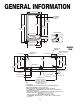
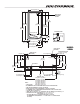
GENERAL INFORMATION 41 7/16 in [105.2 cm] Amp plate & Serial Plate location 64 in [162.6 cm] (Frame Height) 59 in [149.9 cm] 81 1/4 in [206.3 cm] 62 3/8 in [158.4 cm] (Door Height) 83 1/4 in [211.5 cm] 1/2 BUMPER OPTION 30 7/8 in [78.4 cm] COIL 6 13/16 in [17.2 cm]* 31 9/16 in [80.2 cm] 5 1/8 in [13.1 cm] 7 1/2 in [19.1 cm] 16 1/16 in [40.9 cm] PLENUM 8 1/2 in [21.6 cm] 39 1/4 in [99.7 cm] 42 11/16 in [108.4 cm] MODEL ORB PIPING-TO-TOP (OPTIONAL) WIRING-TO-TOP (OPTIONAL) 8 in [20.
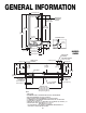
41 7/16 in [105.2 cm] Amp plate & Serial Plate location 68 in [172.7 cm] (Frame Height) 63 in [160.1 cm] 85 1/16 in [216.0 cm] 87 1/16 in [221.1 cm] 66 3/8 in [168.6 cm] (Door Height) 1/2 BUMPER OPTION 30 7/8 in [78.4 cm] COIL 5 1/8 in [13.1 cm] 7 1/2 in [19.1 cm] 16 1/16 in [40.9 cm] PLENUM 8 1/2 in [21.6 cm] 6 13/16 in [17.2 cm]* 31 9/16 in [80.2 cm] 39 1/4 in [99.7 cm] 42 11/16 in [108.4 cm] MODEL ORBH PIPING-TO-TOP (OPTIONAL) WIRING-TO-TOP (OPTIONAL) 8 in [20.3 cm] 10 in [25.
GENERAL INFORMATION 34 5/8 in [88.0 cm] 64 in [162.6 cm] (Frame Height) 62 3/8 in [158.4 cm] (Door Height) 59 in [149.9 cm] 81 1/4 in [206.4 cm] Amp plate & Serial Plate location 83 1/4 in [211.5 cm] 23 1/4 in [59.1 cm] 1/2 BUMPER OPTION PLENUM COIL 5 1/8 in [13.1 cm] 7 1/2 in [19.1 cm] 16 1/4 in [41.3 cm] 8 in [20.3 cm] 6 13/16 in [17.3 cm]* 24 3/16 in [61.4 cm] MODEL ONRB 31 7/8 in [81.0 cm] 35 3/8 in [89.8 cm] PIPING-TO-TOP (OPTIONAL) REAR REFRIGERATION (12 1/4" off of floor) 8 in [20.
34 5/8 in [88.0 cm] Amp plate & Serial Plate location 68 in [172.7 cm] (Frame Height) 66 3/8 in [168.6 cm] (Door Height) 63 in [160.0 cm] 85 1/16 in [216.0 cm] 87 1/16 in [221.1 cm] 23 1/4 in [59.1 cm] 1/2 BUMPER OPTION PLENUM COIL 5 1/8 in [13.1 cm] 7 1/2 in [19.1 cm] 16 1/4 in [41.3 cm] 8 in [20.3 cm] 6 13/16 in [17.3 cm]* 24 3/16 in [61.4 cm] MODEL ONRBH 31 7/8 in [81.0 cm] 35 3/8 in [89.8 cm] PIPING-TO-TOP (OPTIONAL) REAR REFRIGERATION (12 1/4" off of floor) 27 5/16 in [69.
GENERAL INFORMATION 4" 23 3/16" NARROW 31 11/16" STANDARD 2 DOOR CASE 59 1/4" FRONT OF CASE 4" 23 3/16" NARROW 4" 6" 31 11/16" STANDARD 3 DOOR CASE 8' CASE 47 1/2" (3dr CASE) 49 1/8" (8' CASE) 89 1/4" (3dr CASE) 95 1/4" (8' CASE) FRONT OF CASE 23 3/16" NARROW 6" 6" 4" 4" 31 11/16" STANDARD 4 DOOR CASE BASEHORSE LOCATION FOR MODEL ONRB, ONRBH, ORB & ORBH 38 13/16" (4dr CASE) 44 5/8" (12' CASE) 77 3/16" (4dr CASE) 92 5/8" (12' CASE) 119 1/4" (4dr CASE) 143 1/4" (12' CASE) FRONT OF CASE 4"
CASES MOVE ON CASTERS FOR EASIER INSTALLATION ORIGIN2 cases are manufactured and shipped to stores with casters installed on the base frame to make the job of moving cases easier for everyone involved with the manufacturing, shipping and installation process. Casters not only speed up the process, but they also reduce the chance of damage from raising and lowering cases with ”J” bar to place them on dollies, skates or rollers. In most situations, one or two persons can move the case with ease.
LINE UP BASE RAIL BASE RAIL Consult With General Contractor 1 Snap Chalk Lines 2 Ask the general contractor if there have been changes in the building dimensions since the print you are using was issued. Also, ask the points of reference from which you should take dimensions to locate the cases. Mark floor where cases are to be located for the entire lineup. Level Floor. Use Laser Transit Set Shims On Basehorse Locations 4 Leveling is necessary to assure proper case alignment.
CAULK COTTER PIN LOCATION OUTRIGGER FOAM TAPE Remove Outriggers Position Next Case In Line Up 7 Remove cotter pin from outrigger by cutting tie strap. Either pull the outrigger out from the front or insert a crowbar into the tube from the back and push the outrigger out. 8 Roll case approximately 6’ from adjoining case. Remove casters on the end nearest to the next case. Allow casters to remain on opposite end to assist in pushing cases together - then remove them.
TRIM OUT Now that cases have been positioned and leveled, you may proceed to trim-out case lineup. Trim parts have been designed to be applied easily with only a small number of fasteners required. Most external parts are adjustable to achieve almost invisible, snug-fitting joints and a high level of excellence in fit and finish. BUMPER JOINT BUMPER SCREW 1 Adjust polymer master bumper joints, if required. First loosen bumper screws.
STREAMLYNE MASTER BUMPER COLOR BAND 7 Insert exterior cornice joint at every case joint. The exterior cornice joints are shipped loose with each case 8 Close joints on color band by sliding the panels together. The color band can be moved left or right as required to allow adjustment. SCREW EXTERNAL BUMPER JOINT 9 If the case has a Streamlyne front style the bumper may be shipped loose in the case. Before installing bumper on the case install the external bumper joint on the Streamlyne bumper.
REFRIGERATION PIPING The expansion valve and other controls are located on the left-hand side of the case, are accessible without lifting the fan plenum, and may be reached by lifting only the left hand deck pan. Refrigeration components and the coil outlet hole are located to provide the best access for installation and maintenance. As the diagrams below indicates, the coil outlet hole is positioned forward on the right hand side of the case, fully visible in front of the fan plenum.
PLUMBING The drain outlet is located front and center of the cases for convenient access and is especially molded out of ABS material. The “P” trap, furnished with the case, is constructed of schedule 40 PVC pipe. Care should be given to assure that all connections are water tight and sealed with the appropriate PVC or ABS cement. The kickplate is shipped loose with the case for field installation, therefore you should have open access to the drain line area.
ELECTRICAL HOOKUP Electrical hookups are made to a junction box located at the bottom left hand front of the case. At the owners option the case made be wired to a junction box located on the top left rear of the case. For case-to-case wiring, run “greenfield”, or other conduit, between junction boxes.
BALLASTS ACCESS The electronic ballasts that operate the vertical prism door lights are located in the door frame for Anthony® door frames. ANTHONY® FRAMES LIGHT MULLION 3. BALLAST 1. CORNER BEAD 1. CORNER BEAD DOOR 2. ACCESS COVER STEPS TO REPLACE THE BALLAST ANTHONY® FRAMES 1. REMOVE CORNER BEADS (2) 2. REMOVE ACCESS COVER 3.
BALLAST LOCATIONS POWER LEADS FILTER LAMP 3 LAMP 2 LAMP 1 BALLAST FOR LAMP 2 2 DOOR MODELS BALLAST FOR LAMPS 1 & 3 LAMP LEADS POWER LEADS FILTER LAMP 4 BALLAST FOR LAMPS 3 & 4 LAMP 3 LAMP 2 LAMP 1 BALLAST FOR LAMPS 1 & 2 LAMP LEADS 18 3 DOOR MODELS
4 DOOR MODELS POWER LEADS FILTER LAMP 4 LAMP 5 BALLAST FOR LAMPS 4 & 5 BALLAST FOR LAMP 3 LAMP 3 LAMP 2 LAMP 1 BALLAST FOR LAMPS 1 & 2 LAMP LEADS 5 DOOR MODELS POWER LEADS FILTER 19 LAMP 5 LAMP 4 LAMP LEADS LAMP 6 BALLAST FOR LAMPS 5 & 6 BALLAST FOR LAMPS 3 & 4 LAMP 3 LAMP 2 LAMP 1 BALLAST FOR LAMPS 1 & 2
ORB, ORBH, WIRING DIAGRAMS-ONRB & ONRBH 15 16 2 DOOR 20
ORB, ORBH, WIRING DIAGRAMS-ONRB & ONRBH 15 16 3 DOOR - 8’ 21
ORB, ORBH, WIRING DIAGRAMS-ONRB & ONRBH 15 16 4 DOOR - 12’ 22
WHITE 16 15 BLACK BLACK GREEN 12 11 WHITE WHITE L1 23 21 20 19 L1 L2 L2 BLACK WHITE BLACK YELLOW WHITE ORANGE TO COMP. ROOM { WHITE ANTI- { COND. HEATERS YELLOW PURPLE TO COMP. ROOM { BLACK { 120V LIGHTS BLACK { OPT DEFROST 208/240V BLUE 5 3 4 P4 FRONT J.BOX OR J.BOX ON TOP FAN MOTOR M1 M2 WHITE BLACK BLUE WHITE BLACK M3 FAN MOTOR FAN MOTOR CASE LIGHT BIMETAL DISC THERMOSTAT BLACK WHITE BLACK SCAN-X SENSOR BUTTON LOC.-TOP WHITE EVAP.
WHITE 16 15 BLACK BLACK GREEN WHITE 12 11 L1 MULLION HEATER 23 21 20 19 L1 L2 L2 5 3 4 M1 FRONT J.BOX OR J.BOX ON TOP FAN MOTOR EVAP. FAN BIMETAL DISC THERMOSTAT M2 M3 BLACK J4 WHITE FAN MOTOR WHITE BLACK BLUE BLACK FAN MOTOR CASE LIGHT BIMETAL DISC THERMOSTAT BLACK WHITE BLACK WHITE BLACK WHITE BLACK BLACK BLUE WHITE ORANGE TO COMP. ROOM { WHITE ANTI- { COND. HEATERS YELLOW PURPLE TO COMP.
WIRING DIAGRAMS- 25 GFI
CASE OPERATION Glass Door Reach-in Beverage Merchandiser ORB - 2, 3, 4, 5 & 6-door Electrical Data Model ORB 2-door 3-door 4-door 5-door 6-door Standard Fans High Efficiency Fans Anti-Condensate Heaters Defrost Heaters Fans per Case Amps Watts Amps Watts Amps Watts Amps Watts Amps Watts 2 3 4 5 6 1.00 1.50 2.00 2.50 3.00 60 90 120 150 180 0.31 0.46 0.61 0.77 0.92 18.4 27.6 36.8 46.0 55.2 1.01 1.49 1.96 2.40 2.92 121 179 235 288 350 4.39 4.96 6.51 7.96 9.
High Glass Door Reach-in Beverage Merchandiser ORBH - 2, 3, 4, 5, 6-door, 8’ & 12’ Electrical Data Model ORBH Standard Fans High Efficiency Fans Anti-Condensate Heaters 120 Volts 120 Volts 120 Volts Defrost Heaters 240 Volts 208 Volts Fans per Case Amps Watts Amps Watts Amps Watts Amps Watts Amps Watts 2 3 4 5 6 3 4 1.00 1.50 2.00 2.50 3.00 1.50 2.00 60 90 120 150 180 90 120 0.31 0.46 0.61 0.77 0.92 0.70 0.93 18.4 27.6 36.8 46.0 55.2 42 56 1.06 1.55 2.07 2.54 3.07 1.61 2.
CASE OPERATION Narrow Glass Door Reach-in Beverage Merchandiser ONRB - 2, 3, 4 & 5-door Electrical Data Model ONRB Standard Fans High Efficiency Fans Anti-Condensate Heaters 120 Volts 120 Volts 120 Volts Defrost Heaters 208 Volts 240 Volts Fans per Case Amps Watts Amps Watts Amps Watts Amps Watts Amps Watts 2 3 4 5 1.00 1.50 2.00 2.50 60 90 120 150 0.31 0.46 0.61 0.77 18.4 27.6 36.8 46.0 1.01 1.49 1.96 2.40 121 179 235 288 4.39 4.96 6.51 7.96 914 1032 1355 1655 5.06 5.71 7.
High Narrow Glass Door Reach-in Beverage Merchandiser ONRBH - 2, 3, 4 & 5-door Electrical Data Model Standard Fans High Efficiency Fans Anti-Condensate Heaters 120 Volts 120 Volts 120 Volts Defrost Heaters 208 Volts 240 Volts Fans per Case Amps Watts Amps Watts Amps Watts Amps Watts Amps Watts 2 3 4 5 1.00 1.50 2.00 2.50 60 90 120 150 0.31 0.46 0.61 0.77 18.4 27.6 36.8 46.0 1.06 1.55 2.07 2.54 127 186 248 305 4.39 4.96 6.51 7.96 914 1032 1355 1655 5.06 5.71 7.55 9.
DEFROST AND TEMP CONTROL This case is equipped with either Electric, Hot Gas, or Timed-Off defrost at the owners option. The sensor bulb and probe for electric defrost termination control, the sensor bulb for timed-off defrost termination control, and the sensor bulb for temperature control are all located behind the rear baffle at the location shown in illustration 1 below. The discharge air probe is located behind a 3 1/2” plug button on the top flue panel also shown in diagram 1.
AIR FLOW AND PRODUCT LOADING Cases have been designed to provide maximum product capacity within the refrigerated air envelope. It is important that you do not overload the food product display so that it impinges on the air flow pattern. Overloading will cause malfunction and the loss of proper temperature levels, particularly when discharge and return air sections are covered. Please keep products within the load limit lines shown on these diagrams. DISCHARGE..............1 LOAD LIMIT...............
USE AND MAINTENANCE CASE CLEANING Case is designed to facilitate cleaning. There is a wide radius formed on the front and back of the inside bottom of the tank (ORB & ORBH) that helps accelerate liquid flow and eliminates difficult-to-clean sharp corners. All surfaces pitch to a deep-drawn drain trough that angles toward the front and center of case where the waste outlet is located for easy access.
USE AND MAINTENANCE FANS 2 The evaporator fans are equipped with either 9 watt fan motors, 1550 RPM’s, or 12 watt fan motors, 1650 RPM’s. Both motors have a counter clockwise rotation when viewed from the shaft end. The fan blades are 8” in diameter and the blades are pitched as shown on the chart below. It is important that the blade pitch be maintained as specified. Do not attempt a field modification by altering the blades.
PARTS ORDERING 23 20 15 10 25 13 12 E02 E08 56 83 82 55 87 88 4 2 17 1 24 78 9 11 81 69 E01 23 E10 E09 E11 E20 34
Model ORB, ORBH, ONRB & ONRBH Location Number 1 2 3 4 9 10 11 12 13 15 17 20 23 24 25 36 55 56 69 78 81 82 83 87 88 E01 E02 E08 E09 E10 E11 E20 Part Descriptions Kickplate, Storm Grey Master Bumper, 3/4, 1/2, Featherstone, Smoke, White, French Vanilla, Black Lower Front Panel, Painted Custom Color (Not Shown) Color Band, Painted Custom Color or Stainless Deck Pan, Painted, Unpainted Wire Shelving, White, With or Without Covers Front Baffle, Aluminum Honeycomb, 1”x 4”x 48” Honeycomb Retainer, Painted Upper
PARTS ORDERING Procedure 1. Contact the Service Parts Department Hill PHOENIX 1925 Ruffin Mill Road Colonial Heights, Virginia 23834 Tel: 800-283-1109 Fax: 804-526-3897 2. Provide the following information about the part you are ordering: • Model number and serial number of the case on which the part is used. • Length of part, if applicable, I.E. 60”, 90”, 120”, 150”, or 180” • Color of part if painted, or color of polymer part. • Whether part is for left hand or right hand application.
APPENDIX - A CLEANING INSTRUCTIONS FOR ANTIFOG COATING Antifog Coating Cleaning Instructions (ANTIFOG B): Materials CAUTION: 1. Only use deionized or distilled water with 2% cleaning solution (P/N 05-14700-0001) to clean the antifog coating. Do not apply cleaning solution full strength! Do not use commercial glass cleaners containing ammonia or alcohol. 2. Only use soft lint-free wipers, such as Kimwipes or Soft-Tech paper wipers.
NOTES 38
WARRANTY HEREINAFTER REFERRED TO AS MANUFACTURER FOURTEEN MONTH WARRANTY. MANUFACTURER’S PRODUCT IS WARRANTED TO BE FREE FROM DEFECTS IN MATERIAL AND WORKMANSHIP UNDER NORMAL USE AND MAINTENANCE FOR A PERIOD OF FOURTEEN MONTHS FROM THE DATE OF ORIGINAL SHIPMENT. A NEW OR REBUILT PART TO REPLACE ANY DEFECTIVE PART WILL BE PROVIDED WITHOUT CHARGE, PROVIDED THE DEFECTIVE PART IS RETURNED TO MANUFACTURER. THE REPLACEMENT PART ASSUMES THE UNUSED PORTION OF THE WARRANTY.
Warning Maintenance & Case Care When cleaning cases the following must be performed PRIOR to cleaning: To avoid electrical shock, be sure all electric power is turned off before cleaning. In some installations, more than one switch may have to be turned off to completely de-energize the case. Do not spray cleaning solution or water directly on fan motors or any electrical connections. All lighting receptacles must be dried off prior to insertion and re-energizing the lighting circuit.