SD 4500-A22 English Printed: 11.08.
Printed: 11.08.
1 Information about the documentation 1.1 About this documentation • • • Read this documentation before initial operation or use. This is a is a prerequisite for safe, trouble-free handling and use of the product. Observe the safety instructions and warnings in this documentation and on the product. Always keep the operating instructions with the product and make sure that the operating instructions are with the product when it is given to other persons. 1.2 Explanation of symbols used 1.2.
The type designation and serial number are printed on the type identification plate. ▶ Write down the serial number in the table below. You will be required to state the product details when contacting Hilti Service or your local Hilti organization to inquire about the product. Product information Type: Generation: Serial number: SD 5000 A-22 SD 4500 A-22 01 2 Safety ***** For internal use only ***** 11.08.2016 / 12:48:13 - H2\DOK-Projekt\System\SD_5000-A22\ENU\SD4500_P3 2.
Battery tool use and care ▶ Recharge only with the charger specified by the manufacturer. A charger that is suitable for one type of battery pack may create a risk of fire when used with another battery pack. ▶ Use power tools only with specifically designated battery packs. Use of any other battery packs may create a risk of injury and fire.
▶ Take breaks between working and do physical exercises to improve the blood circulation in your fingers. Exposure to vibration during long periods of work can lead to disorders of the blood vessels and nervous system in the fingers, hands and wrists. Electrical safety ▶ Before starting work, check the working area for concealed electric cables or gas and water pipes. If you damage an electric cable accidentally, external metal parts of the power tool may become live and present a risk of electric shock.
5 Printed: 11.08.2016 | Doc-Nr: PUB / 5295850 / 000 / 00 ***** For internal use only ***** 11.08.
6 Printed: 11.08.2016 | Doc-Nr: PUB / 5295850 / 000 / 00 ***** For internal use only ***** 11.08.
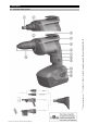
***** For internal use only ***** 11.08.2016 / 12:48:13 - H2\DOK-Projekt\System\SD_5000-A22\ENU\SD4500_P3 3 Description 3.1 Overview of the product 7 Printed: 11.08.
@ ; = % & ( ) Chuck Power tool / accessory interface (snap-on connection) Universal hook Motor cooling air intake Grip Motor cooling air intake Forward / reverse selector switch with safety lock + § / : ∙ $ Control switch (with electronic speed control) Lockbutton for continuous operation Belt hook Charge state and fault display (Li-ion battery) Battery release buttons Depth gauge 3.2 Intended use ***** For internal use only ***** 11.08.
Maximum torque Socket/bit drive Screw length Screw diameter 7.0 ftlbf (9.5 Nm) Hex socket 1/4" ≤ 2.2 in (≤ 55 mm) ≤ 0.17 in (≤ 4.2 mm) 5 Preliminary and finishing work 5.1 Charging the battery ▶ Use an approved charger to charge the battery. 5.2 Inserting the battery WARNING Risk of injury! Inadvertent starting of the screwdriver. ▶ Before fitting the battery, check that the screwdriver is switched off and that the forward / reverse switch is in the middle position (i.e. safety lock engaged).
***** For internal use only ***** 11.08.2016 / 12:48:13 - H2\DOK-Projekt\System\SD_5000-A22\ENU\SD4500_P3 5.3 Fitting the belt hook in the alternative position 1. 2. 3. 4. Press both battery release buttons simultaneously and pull the battery out of the screwdriver. Unscrew both belt hook retaining screws. Bring the belt hook and threaded piece into place on the other side of the tool. Reinsert and tighten the two retaining screws. 5.
1. Pull the depth gauge away from the power tool, releasing the snap-on connection. 2. Push the chuck towards the screwdriver, turning the chuck slightly at the same time, and then hold it in this position. 3. Remove the accessory tool with your other hand. 4. Insert the desired accessory tool in the chuck, pushing it into the screwdriver as far as it will go. 5.7 Removing the battery ▶ Press both battery release buttons simultaneously and pull the battery out of the screwdriver. 11 Printed: 11.08.
6 Driving and removing screws ***** For internal use only ***** 11.08.2016 / 12:48:13 - H2\DOK-Projekt\System\SD_5000-A22\ENU\SD4500_P3 6.1 Driving screws WARNING Electrical hazards There is a risk of electric shock if a screw is driven into a concealed electric cable and, at the same time, the bit holder or depth gauge is touched. ▶ 1. 2. 3. 4. Hold the screwdriver only by the grip when driving or removing screws. Set the screwdriver to forward rotation.
6.5 Screwdriver / depth gauge interface 1. Pull the depth gauge away from the power tool, releasing the snap-on connection. 2. Pull the depth gauge forward, away from the power tool. Note With the drive spindle exposed in this way, the following operations can be carried out: Removing screws (set to reverse rotation), changing bits, changing bit holders, changing to magazine operation, redriving screws.
Trouble or fault ***** For internal use only ***** 11.08.2016 / 12:48:13 - H2\DOK-Projekt\System\SD_5000-A22\ENU\SD4500_P3 The screwdriver doesn’t work and one LED blinks. Possible cause Low battery. Action to be taken ▶ The battery is too hot or too cold. ▶ The screwdriver doesn’t work and all four LEDs blink. The overload cut-out has been activated. ▶ The control switch can’t be pressed, i.e. the switch is locked. The safety lock is engaged.
Printed: 11.08.
Printed: 11.08.2016 | Doc-Nr: PUB / 5295850 / 000 / 00 ** Hilti = registered trademark of Hilti Corp.