UD 16 / UD 30 Bedienungsanleitung de Operating instructions en Mode d’emploi fr Manual de instrucciones es Istruzioni d’uso it Gebruiksaanwijzing nl Brugsanvisning da Bruksanvisning no Bruksanvisning sv Käyttöohje fi Manual de instruções pt Οδηγιες χρησεως el Lietoßanas pamåcîba lv Instrukcija lt Kasutusjuhend et ar
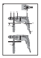
1 1 5 6 1 7 2 UD 30 8 9 4 2 +≠ 1 3 2 UD 16
2 3 4 1 1 1 2 1 3 2 3/4 2 2/5 5 4 5 2 2 3 3/4 1 6 7 3 1 4 2 4 6 2 5 1 8 3 9 1 2 2 1 4 3
10 11 2 3 1 12 1 3 4 2
UD 16 / UD 30 drill It is essential that the operating instructions are read before the power tool is operated for the first time. Always keep these operating instructions together with the power tool. Ensure that the operating instructions are with the power tool when it is given to other persons. Contents 1. General information 2. Description 3. Accessories 4. Technical data 5. Safety rules 6. Before use 7. Operation 8. Care and maintenance 9. Troubleshooting 10. Disposal 11.
Obligation signs Wear a hard hat Wear eye protection en Wear breathing protection Wear ear protection Location of identification data on the power tool The type designation, item number, year of manufacture and technical status can be found on the type identification plate on the machine or tool. The serial no. can be found on the underside of the motor housing.
Working on materials hazardous to the health (e.g. asbestos) is not permissible. The power tool may be used only in a dry environment. Do not use the power tool where there is a risk of fire or explosion. 2.2 Chuck Keyless chuck or Key chuck with key en 2.3 Switches Control switch with electronic speed control Lockbutton for sustained operation Function selector switch Forward / reverse switch 2.4 Grips Vibration‐absorbing side handle with depth gauge Vibration‐absorbing grip 2.
UD 30 applications Insert tool type Drilling in wood Twist drills Forstner drill bits Hole saws Auger bits Flat bits (not self‐ cutting) Drywall screws en Driving Drill bit sizes, 1st gear Drill bit sizes, 2nd gear Max. 25 mm Max. 40 mm Max. 50 mm Max. 20 mm Max. 30 mm Max. 20 mm Max. 25 mm ‐ ‐ Max. 30 mm 6/60 mm ‐ 2.6 Items supplied as standard 1 1 1 1 1 Power tool with side handle Depth gauge Chuck key (with keyed chuck) Operating instructions Hilti cardboard box or toolbox 2.
Never operate other power tools or appliances from the generator or transformer at the same time. Switching other power tools or appliances on and off may cause undervoltage and / or overvoltage peaks, resulting in damage to the power tool. 3. Accessories en The list of insert tools can be found in Section 2 under “Possible applications”. Keyless chuck Key chuck Chuck key (with keyed chuck) 4. Technical data Right of technical changes reserved.
Noise and vibration information (measured in accordance with EN 60745 ): Typical A‐weighted sound power level 97 dB (A) Typical A‐weighted emission sound pressure level 86 dB (A) 3 dB (A) Uncertainty for the given sound level en Triaxial vibration values (vibration vector sum) Screwdriving without impact action, ah Uncertainty (K) Measured in accordance with EN 60745‑2‑2 < 2.5 m/s² 1.
b) Use safety equipment. Always wear eye protection. Safety equipment such as dust mask, non‐skid safety shoes, hard hat, or hearing protection used for appropriate conditions will reduce personal injuries. c) Avoid accidental starting. Ensure the switch is in the off‐position before plugging in. Carrying power tools with your finger on the switch or plugging in power tools that have the switch on invites accidents. d) Remove any adjusting key or wrench before turning the power tool on.
side. Parts breaking away could fall out and / or fall down and injure other persons. m)Always engage 1st gear when mixing. This will help to avoid splashing or spillage. Wear protective gloves. 5.2.2 Power tool use and care en a) Secure the workpiece. Use clamps or a vice to secure the workpiece. The workpiece is thus held more securely than by hand and both hands remain free to operate the power tool.
6. Before use 6.1 Fitting and adjusting the side handle 2 CAUTION Remove the depth gauge from the side handle and the insert tool from the chuck in order to avoid injury. 1. Disconnect the supply cord plug from the power outlet. 2. Release the side handle clamping band by turning the handle counterclockwise. 3. CAUTION With the UD 16 it is essential to ensure that the sleeve is fitted in the grip section of the side handle.
used. Splintering material presents a risk of injury to the eyes and body. CAUTION The work generates noise. Wear ear protectors. Exposure to noise can cause hearing loss. en CAUTION The insert tool and the chuck get hot during use. Wear protective gloves when changing insert tools. 7.2.1 Keyless chuck CAUTION Disconnect the supply cord plug from the power outlet. NOTE Use the key supplied to open the chuck and to tighten it after inserting a tool. 7.2.2.1 Opening the key chuck 6 1.
7.2.3.1 Rotary drilling, 1st and 2nd gear 8 1. Turn the function selector switch to the 1st or 2nd gear rotary drilling position until it engages. It may be necessary to turn the drive spindle slightly. 2. Bring the side handle into the desired position and check that it is fitted correctly and secured. 3. Plug the supply cord into the power outlet. 4. Position the power tool and drill bit at the point where the hole is to be drilled. 5.
en 2. Grip the flat section of the drive spindle with a 17 mm AF open‐end wrench. 3. Grip the hexagonal steel with a suitable wrench. 4. Turn the 17 mm AF open‐end wrench in a counterclockwise direction. The key chuck will be unscrewed from the drive spindle. 7.3.3 Fitting the keyless chuck 1. Screw the keyless chuck onto the drive spindle by hand as far as it will go. 2. Grip the flat section of the drive spindle with a 17 mm AF open‐end wrench. 3.
Fault Possible cause Remedy The power tool doesn’t start. The supply cord or plug is defective. Have it checked by a trained electrical specialist and replaced if necessary. Have it checked by a trained electrical specialist and replaced if necessary. Use an extension cord of an approved length and / or of adequate gauge. Press the control switch as far as it will go. Set the forward/reverse switch to forward rotation. Hone the drill bit or replace it. Retighten the chuck.
en ment as a result of normal wear and tear are not covered by this warranty. warranties of merchantability or fitness for a particular purpose are specifically excluded. Additional claims are excluded, unless stringent national rules prohibit such exclusion. In particular, Hilti is not obligated for direct, indirect, incidental or consequential damages, losses or expenses in connection with, or by reason of, the use of, or inability to use the tool for any purpose.
Hilti Corporation 273763 / D 273763 Hilti = registered trademark of Hilti Corp., Schaan W 3243 1107 00-Pos. 1 1 Printed in China © 2007 Right of technical and programme changes reserved S. E. & O. *273763* LI-9494 Schaan Tel.: +423 / 234 21 11 Fax: +423 / 234 29 65 www.hilti.