
Product Technical Guide Excerpt for HSL-3 Heavy Duty Expansion Anchor


277
Anchor Fastening Technical Guide, Edition 19
Anchor Fastening Technical Guide Edition 19 | 3.0 ANCHORING SYSTEMS | 3.3.2 HSL-3 HEAVY-DUTY EXPANSION ANCHORS
Hilti, Inc. (U.S.) 1-800-879-8000 | en español 1-800-879-5000 | www.hilti.com | Hilti (Canada) Corporation | www.hilti.com | 1-800-363-4458
3.3.2
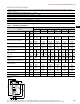
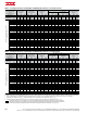
Table 12 - Hilti HSL-3 anchors factored resistance with concrete/pullout failure in uncracked concrete
1,2,3,4,5
Nominal
anchor
diameter
Effective
embed.
in. (mm)
Tension - N
r
Shear - V
r
ƒ'
c
= 20 MPa
(2,900psi)
lb (kN)
ƒ'
c
= 25 MPa
(3,625 psi)
lb (kN)
ƒ'
c
= 30 MPa
(4,350 psi)
lb (kN)
ƒ'
c
= 40 MPa
(5,800 psi)
lb (kN)
ƒ'
c
= 20 MPa
(2,900 psi)
lb (kN)
ƒ'
c
= 25 MPa
(3,625 psi)
lb (kN)
ƒ'
c
= 30 MPa
(4,350 psi)
lb (kN)
ƒ'
c
= 40 MPa
(5,800 psi)
lb (kN)
M8
60 2,945 3,290 3,605 4,165 3,035 3,395 3,720 4,295
(2.4) (13.1) (14.6) (16.0) (18.5) (13.5) (15.1) (16.5) (19.1)
M10
70 3,825 4,280 4,685 5,415 7,655 8,560 9,375 10,825
(2.8) (17.0) (19.0) (20.9) (24.1) (34.0) (38.1) (41.7) (48.2)
M12
80 4,675 5,230 5,725 6,615 9,350 10,455 11,455 13,225
(3.1) (20.8) (23.3) (25.5) (29.4) (41.6) (46.5) (50.9) (58.8)
M16
100 6,535 7,305 8,005 9,240 13,070 14,615 16,005 18,485
(3.9) (29.1) (32.5) (35.6) (41.1) (58.1) (65.0) (71.2) (82.2)
M20
125 9,135 10,210 11,185 12,915 18,265 20,420 22,370 25,830
(4.9) (40.6) (45.4) (49.8) (57.5) (81.3) (90.8) (99.5) (114.9)
M24
150 12,005 13,425 14,705 16,980 24,010 26,845 29,405 33,955
(5.9) (53.4) (59.7) (65.4) (75.5) (106.8) (119.4) (130.8) (151.0)
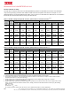
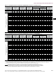
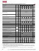
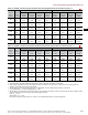
Table 13 - Hilti HSL-3 anchor steel factored resistance with concrete / pullout failure in cracked concrete
1,2,3,4,5
Nominal
anchor
diameter
Effective
embed.
in. (mm)
Tension - N
r
Shear - V
r
ƒ'
c
= 20 MPa
(2,900psi)
lb (kN)
ƒ'
c
= 25 MPa
(3,625 psi)
lb (kN)
ƒ'
c
= 30 MPa
(4,350 psi)
lb (kN)
ƒ'
c
= 40 MPa
(5,800 psi)
lb (kN)
ƒ'
c
= 20 MPa
(2,900 psi)
lb (kN)
ƒ'
c
= 25 MPa
(3,625 psi)
lb (kN)
ƒ'
c
= 30 MPa
(4,350 psi)
lb (kN)
ƒ'
c
= 40 MPa
(5,800 psi)
lb (kN)
M8
60 1,970 2,200 2,410 2,785 2,125 2,375 2,605 3,005
(2.4) (8.8) (9.8) (10.7) (12.4) (9.5) (10.6) (11.6) (13.4)
M10
70 3,150 3,520 3,855 4,455 7,655 8,560 9,375 10,825
(2.8) (14.0) (15.7) (17.2) (19.8) (34.0) (38.1) (41.7) (48.2)
M12
80 4,675 5,230 5,725 6,615 9,350 10,455 11,455 13,225
(3.1) (20.8) (23.3) (25.5) (29.4) (41.6) (46.5) (50.9) (58.8)
M16
100 6,535 7,305 8,005 9,240 13,070 14,615 16,005 18,485
(3.9) (29.1) (32.5) (35.6) (41.1) (58.1) (65.0) (71.2) (82.2)
M20
125 9,135 10,210 11,185 12,915 18,265 20,420 22,370 25,830
(4.9) (40.6) (45.4) (49.8) (57.5) (81.3) (90.8) (99.5) (114.9)
M24
150 12,005 13,425 14,705 16,980 24,010 26,845 29,405 33,955
(5.9) (53.4) (59.7) (65.4) (75.5) (106.8) (119.4) (130.8) (151.0)
1 See section 3.1.8 to convert design strength value to ASD value.
2 Linear interpolation between embedment depths and concrete compressive strengths is not permitted.
3 Apply spacing, edge distance, and concrete thickness factors in tables 6 to 9 as necessary. Compare to the steel values in table 10.
The lesser of the values is to be used for the design.
4 Tabular values are for normal weight concrete only. For lightweight concrete multiply design strength by λ
a
as follows:
for sand-lightweight, λ
a
= 0.68; for all-lightweight, λ
a
= 0.60
5 Tabular values are for static loads only. Seismic design is not permitted for uncracked concrete. For seismic tension loads, multiply cracked
concrete tabular values in tension only by the following reduction factors:
M24 - α
N,seis
= 0.62
All other sizes - α
N,seis
= 0.75
No reduction needed for seismic shear. See section 3.1.8 for additional information on seismic applications.