Printed: 18.10.
Printed: 18.10.
1 Information about the documentation 1.1 About this documentation • • • Read this documentation before initial operation or use. This is a prerequisite for safe, trouble-free handling and use of the product. Observe the safety instructions and warnings in this documentation and on the product. Always keep the operating instructions with the product and make sure that the operating instructions are with the product when it is given to other persons. 1.2 Explanation of signs used 1.2.
Drilling performance indicator 1.4 Product-dependent symbols 3-way valve Position for wet drilling Position for dry drilling Core bit draining position Illustrations At temperatures below 4 °C the cooling circuit must be drained as described before breaks of an hour or longer. Operate the system only with a fully functional PRCD. Top: An additional means of securing the drill stand must be employed when the machine is used for horizontal drilling with the vacuum securing method. 1.
▶ Write down the serial number in the table below. You will be required to state the product details when contacting Hilti Service or your local Hilti organization to inquire about the product. Product information Diamond core drilling machine Generation Serial no. DD 350-CA 01 1.6 Declaration of conformity We declare, on our sole responsibility, that the product described here complies with the applicable directives and standards.
▶ ▶ ▶ Dress properly. Do not wear loose clothing or jewellery. Keep your hair and clothing away from moving parts. Loose clothes, jewellery or long hair can be caught in moving parts. If devices are provided for the connection of dust extraction and collection facilities, ensure these are connected and properly used. Use of dust collection can reduce dust-related hazards. Do not let familiarity gained from frequent use of tools allow you to become complacent and ignore tool safety principles.
▶ ▶ ▶ ▶ Do not touch rotating parts. Switch the power tool on only after it is in position at the workpiece. Touching rotating parts, especially rotating accessory tools, can result in injury. Avoid skin contact with drilling slurry. Dust from materials such as lead-based paint, certain types of wood and concrete/masonry/stone containing quartz, minerals or metal can be harmful to health.
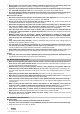
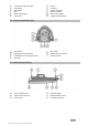
3 Description 3.1 Product overview 6 English Printed: 18.10.
@ ; = % & ( Controls and indicators panel Carrying bar Rating plate Grip Water drainage plug 3-way valve ) + § / : ∙ Chuck Connector Supply cord guide Water connection Water flow regulator Supply cord with PRCD & ( ) OFF switch Rebar button (iron boost) Service indicator % & ( Pressure gauge Wheel assembly mount Leveling screws (4x) 3.2 Controls and indicators panel @ ; = % Gear switch Drilling performance indicator Temperature monitoring/ground fault ON switch 3.
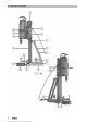
3.4 Overview, accessories 8 English Printed: 18.10.
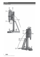
DD-HD 30 drill stand (accessory) @ Limit stop with rail cap ; Leveling indicators (2x) = Carriage % Carrying handle (2x) & Brace ( Leveling screws (3x) ) Wheel assembly mount + Base plate § Rail Set of fasteners for drill stand (accessory) W Clamping nut Water collection system (accessory) R Seal T Water collector / : ∙ $ £ | ¡ Q Carriage lock Eccentric pin (for securing the equipment) Hand wheel Anchor position Reduction gearing (1:3) Direct drive (1:1) Rating plate Hole center indicator E Clamping spi
4 Technical data 4.1 Diamond core drilling machine Note For rated voltage, rated current, frequency and/or input power, refer to the country-specific type identification plate. If the tool is powered by a generator or transformer, the generator or transformer’s power output must be at least twice the rated input power shown on the rating plate of the tool. The operating voltage of the transformer or generator must always be within +5% and -15% of the rated voltage of the tool. DD 350 Chuck BL Max.
5.1.1 Setting up the drill stand 1. 2. 3. 4. Slacken the screw at the top at the brace and the screw at the bottom at the pivot joint of the rail. Bring the rail into the vertical position. Tighten the screw at the top at the brace and the screw at the bottom at the pivot joint of the rail. Install the cover with the integral end stop at the top end of the rail. 5.1.2 Installing the hand wheel Note You can install the hand wheel on the right or left side of the carriage on two different shafts.
1. Set the anchor for the base plate 330 mm (13 inch) from the hole center. Note If you work with a spacer, increase the distance accordingly. 2. 3. 4. 5. 6. 7. Screw the clamping spindle into the anchor. Slip the drill stand over the spindle and align it. Screw the clamping nut on to the spindle but do not tighten it. Use the leveling screws to level the base plate. Use a suitable open-end wrench to tighten the clamping nut on the clamping spindle. Check that the drill stand is secure. 5.1.
1. 2. 3. 4. 5. 6. 7. Turn all the leveling screws until they project approx. 5 mm underneath the vacuum base plate. Connect the vacuum connector on the vacuum base plate to the vacuum pump. Set the drill stand on the vacuum base plate. Use the screw supplied, complete with its washer, to secure the drill stand to the vacuum base plate. Locate the center point of the hole to be drilled. Draw a line approximately 800 mm in the direction in which the core drilling system is to stand.
1. Slacken the screw at the top at the brace and the screw at the bottom at the pivot joint of the rail. 2. Adjust the rail to the desired position. 3. Tighten the screw at the top at the brace and the screw at the bottom at the pivot joint of the rail. 5.1.6 Extending the rail Note When starting a hole, use only a core bit or extended core bit with a maximum total length of 650 mm (25 1/2 in). A depth gage on the rail can be used as an additional end stop.
Note When core bits of diameter > 300 mm (11 1/2 in) are used, the distance between drill stand and drilling axis has to be increased by installing one or two spacers. The hole center indicator is no longer functional when spacers are used. Insert the spacer or spacers without the diamond core drilling machine mounted on the drill stand. 1. 2. 3. 4. 5. 6. Lock the carriage on the rail with the carriage lock. Pull out the eccentric pin for locking the diamond core drilling machine on the carriage.
5.1.9 Installing the water supply connection CAUTION Risk of personal injury and material damage The hose may become damaged if it is used incorrectly. ▶ ▶ ▶ ▶ ▶ Regularly check the hoses for damage and make sure that the maximum permissible water supply pressure of 6 bar is not exceeded. Make sure that the hose does not come into contact with rotating parts. Make sure that the hose is not damaged as the carriage advances. Maximum water temperature: 40 °C.
2. Slip the water collector holder behind the screw from below. 3. Securely tighten the screw. 4. Position the water collector, with seal and water collector sealing disc installed, between the two movable arms of the holder. 5. Secure the water collector to the holder with the two screws. 6. Connect a wet-type industrial vacuum extractor to the water collector or establish a hose connection through which the water can drain away. 5.1.
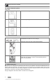
5.2 Types of work 5.2.1 Keep the danger zone clear The shaded area in the illustration defines the danger zone round the diamond core drilling machine. • • When operating the machine, always keep at least 15 cm clear of the core bit. Position yourself behind the drill stand while drilling is in progress. 5.2.2 Selecting the speed Note Press the switch only when the tool is stationary. 1. Set the selector switch to suit the diameter of the core bit used. 2.
5.2.5 Operating the diamond core drilling machine WARNING Risk of personal injury and material damage The diamond core drilling machine may become damaged and the risk of electric shock is increased. ▶ Use of the water collection system in conjunction with a wet-type industrial vacuum cleaner is a mandatory requirement for wet drilling overhead. DANGER Risk of personal injury and material damage The wet-type industrial vacuum cleaner switches on and off with a delay.
5.2.6 Operating the diamond core drilling machine dry DANGER Risk of personal injury and material damage The diamond core drilling machine may become damaged and the risk of electric shock is increased. ▶ When drilling in an upward direction, stop working if the suction removal system stops working (e.g. the wet-type industrial vacuum cleaner is full). WARNING Risk of personal injury and material damage The water collector cannot function correctly during drilling in an upward direction at an angle.
1. If the following conditions are met, also take this action: Conditions: Drilling upward 2. 3. 4. 5. ▶ Set the 3-way valve to the middle position to drain the water from the core bit. Remove the diamond core bit from the hole. Switch off the diamond core drilling machine. Lock the carriage on the rail with the carriage lock. Switch off the wet-type industrial vacuum cleaner, if used. 5.2.8 Procedure for dealing with a jammed core bit If the bit jams the safety clutch disengages.
5.2.10 Removing the diamond core drilling machine 1. 2. 3. 4. 5. 6. Lock the carriage on the rail with the carriage lock. Check to ensure that it is securely fastened. Hold the diamond core drilling machine securely with one hand on the carrying grip. Release the eccentric pin in the lock of the diamond core drilling machine. Pull out the eccentric pin. Remove the diamond core drilling machine from the carriage. Push the eccentric pin into the carriage as far as it will go.
2. Use a 19 mm open-end wrench to turn the adjusting screws so that the rollers are pressed slightly against the rail. 3. Tighten the adjusting screws firmly. The carriage is correctly adjusted when it remains in position without a diamond core drilling machine fitted and moves down when the drilling machine is fitted. 7 Transport and storage • • • • Do not transport electric tools with accessory tools fitted. Always unplug the supply cord before storing an electric tool or appliance.
Malfunction The drilling speed is decreasing. The diamond core bit doesn’t rotate. The handwheel can be turned without resistance. Possible cause The diamond core bit is polished. Action to be taken ▶ The volume of water is too high. ▶ The water flow rate is too low. ▶ The carriage lock is engaged. ▶ The diamond core bit has become jammed in the base material. ▶ Reduce the volume of water using the water volume regulator (ensure that the volume of water is at least 0.5 l/min as required).
Malfunction The drilling system has too much play. Possible cause The carriage has too much play. Action to be taken ▶ Screws / bolts on the drill stand are ▶ loose. The drill stand is inadequately fastened. ▶ Adjust the play between the rail and carriage. → page 22 Check the security of screws / bolts on the drill stand and tighten them if necessary. Fasten the drill stand more securely. 8.
Dispose of this solid portion of the drilling or sawing slurry at a construction waste disposal location. Neutralize the remaining water from the drilling or sawing slurry (alkaline, pH-value > 7) by adding an acidic neutralizing agent or dilute it by adding a large quantity of water before allowing it to enter the sewerage system. ▶ ▶ 10 Manufacturer’s warranty Please contact your local Hilti representative if you have questions about the warranty conditions. ▶ 26 English Printed: 18.10.
Printed: 18.10.
Hilti = registered trademark of Hilti Corp., Schaan Printed: 18.10.