
Operating Instruction DD 350-CA (01)


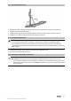


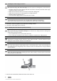
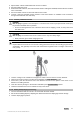

Table Of Contents
- Original operating instructions
- 1 Information about the documentation
- 2 Safety
- 3 Description
- 4 Technical data
- 5 Operation
- 5.1 Preparations at the workplace
- 5.1.1 Setting up the drill stand
- 5.1.2 Installing the hand wheel
- 5.1.3 Securing the drill stand with an anchor
- 5.1.4 Securing the drill stand by vacuum
- 5.1.5 Adjusting the drilling angle when using the drill stand with combination base plate
- 5.1.6 Extending the rail
- 5.1.7 Installing the spacer
- 5.1.8 Securing the diamond core drilling machine to the drill stand
- 5.1.9 Installing the water supply connection
- 5.1.10 installing the water collection system (accessory)
- 5.1.11 Inserting a diamond core bit
- 5.1.12 Setting the depth gage (accessory)
- 5.2 Types of work
- 5.2.1 Keep the danger zone clear
- 5.2.2 Selecting the speed
- 5.2.3 Portable residual current device (PRCD)
- 5.2.4 Using the hole-starting function
- 5.2.5 Operating the diamond core drilling machine
- 5.2.6 Operating the diamond core drilling machine dry
- 5.2.7 Switching off the diamond core drilling machine
- 5.2.8 Procedure for dealing with a jammed core bit
- 5.2.9 Removing the diamond core bit
- 5.2.10 Removing the diamond core drilling machine
- 5.1 Preparations at the workplace
- 6 Care and maintenance
- 7 Transport and storage
- 8 Troubleshooting
- 9 Disposal
- 10 Manufacturer’s warranty

14 English
1. Slacken the screw at the top at the brace and the screw at the bottom at the pivot joint of the rail.
2. Adjust the rail to the desired position.
3. Tighten the screw at the top at the brace and the screw at the bottom at the pivot joint of the rail.
5.1.6 Extending the rail
Note
When starting a hole, use only a core bit or extended core bit with a maximum total length of 650 mm
(25 1/2 in).
A depth gage on the rail can be used as an additional end stop.
After removing the extension rail, reinstall the cover (with integrated end stop) on the drill stand.
Otherwise the safety-relevant end-stop function is not implemented.
1. Remove the cover (with built-in end stop) from the top end of the rail.
2. Install the cover on the extension rail.
3. Insert the cylindrical connector of the extension rail into the end of the rail of the drill stand.
4. Secure the extension rail by turning the eccentric pin.
5.1.7 Installing the spacer
WARNING
Risk of injury. The fastening may become overloaded.
▶ When one or more spacers are used, the contact pressure must be reduced in order to avoid
overloading the fastening.
Printed: 18.10.2017 | Doc-Nr: PUB / 5236055 / 000 / 02