UD 16 / UD 30 Printed: 24.04.
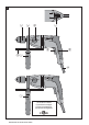
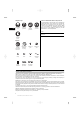
1 1 5 6 1 7 UD 30 2 8 9 4 2 +≠ 1 UD 16 2 3 This Product is Certified Ce produit est homologué Producto homologado por Este produto está registrado C Printed: 24.04.
2 3 4 1 1 1 2 1 3 2 3/4 2 2/5 5 4 5 2 2 3 3/4 1 6 7 2 3 1 4 4 6 2 5 1 8 3 9 1 2 2 1 4 3 Printed: 24.04.
10 11 2 3 1 12 1 3 4 2 Printed: 24.04.
ORIGINAL OPERATING INSTRUCTIONS UD 16 ‑ UD 30 drill It is essential that the operating instructions are read before the power tool is operated for the first time. Always keep these operating instructions together with the power tool. Ensure that the operating instructions are with the power tool when it is given to other persons.
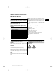
Obligation signs en Wear a hard hat Wear eye protection Wear breathing protection Wear ear protection Location of identification data on the power tool The type designation, item number, year of manufacture and technical status can be found on the type identification plate on the machine or tool. The serial no. can be found on the underside of the motor housing.
Do not use the power tool where there is a risk of fire or explosion. 2.2 Chuck Keyless chuck or Key chuck with key en 2.3 Switches Control switch with electronic speed control Lockbutton for sustained operation Function selector switch Forward / reverse switch 2.4 Grips Vibration-absorbing side handle with depth gauge Vibration-absorbing grip 2.5 Possible applications UD 16 Drill bit sizes, 1st gear Drill bit sizes, 2nd gear Drill bits with smooth shank Stepped drill bits Max. 13 mm (½") Max.
2.6 Items supplied as standard 1 Power tool with side handle 1 Chuck key (with keyed chuck) 1 1 en 1 Depth gauge Operating instructions Hilti cardboard box or toolbox 2.7 Using extension cords Use only extension cords of a type approved for the application and with conductors of adequate cross section. The power tool may otherwise lose performance and the extension cord may overheat. Check the extension cord for damage at regular intervals. Replace damaged extension cords.
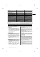
Power tool UD 16 UD 30 Weight in accordance with EPTA procedure 01/2003 Dimensions (L x W x H) 2.6 kg (5.7 lbs) 2.5 kg (5.5 lbs) Speed in 1st gear under no load 342 mm (13.46") x 86 mm (3.39") x 205 mm (8.07") 900/min 337 mm (13.27") x 86 mm (3.39") x 205 mm (8.07") 1,200/min Speed in 2nd gear under no load 2,500/min 3,300/min Chuck ∅ 1.5…13 mm (0.06…0.51") 1.5…13 mm (0.06…0.51") Maximum torque, 1st gear 80 Nm (59 lb/ft) 51 Nm (38 lb/ft) Maximum torque, 2nd gear 29 Nm (21 lb/ft) 18.
en switch or energising power tools that have the switch on invites accidents. d) Remove any adjusting key or wrench before turning the power tool on. A wrench or a key left attached to a rotating part of the power tool may result in personal injury. e) Do not overreach. Keep proper footing and balance at all times. This enables better control of the power tool in unexpected situations. f) Dress properly. Do not wear loose clothing or jewellery. Keep your hair, clothing and gloves away from moving parts.
c) In the event of a power failure or interruption in the electric supply, switch the power tool off, unplug the supply cord and release the switch lockbutton (if applicable). This will prevent accidental restarting when the electric power returns. 5.3.3 Electrical safety Before beginning work, check the working area (e.g. using a metal detector) to ensure that no concealed electric cables or gas and water pipes are present.
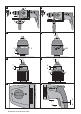
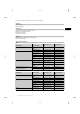
3. en 4. CAUTION With the UD 16 it is essential to ensure that the sleeve is fitted in the grip section of the side handle. Slip the side handle (clamping band) over the chuck and push it onto the collar around the gearing section as far as it will go. CAUTION Check that the ribs on the clamping band engage in the grooves in the collar around the gearing section.
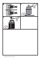
NOTE Depending on the type of chuck fitted, either the broad adjusting ring or the rear gripping ring on the chuck must be held securely by hand. 7.2.1.1 Opening the keyless chuck 4 1. 2. 3. Grip the rotatable sleeve. Turn the sleeve counterclockwise. NOTE First, the locking mechanism will be released automatically. Continue turning the sleeve until the insert tool is released. 7.2.1.2 Closing the keyless chuck 5 1. 2. 3. 4.
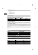
4. 5. en 6. Press the control switch slowly until the screw grips and is guided by the material into which it is being driven. Continue pressing the control switch, applying power appropriate to the material you are working on. Reduce speed toward the end of the screwdriving operation in order to avoid damage. 7.2.4 Control switch with electronic speed control The speed of the power tool can be varied continuously up to maximum speed by slowly increasing pressure on the control switch. 7.2.
8.3 Maintenance WARNING Repairs to the electrical section of the power tool may be carried out only by trained electrical specialists. Check all external parts of the power tool for damage at regular intervals and check that all controls operate faultlessly. Do not operate the power tool if parts are damaged or when the controls do not function faultlessly. If necessary, the power tool should be repaired by Hilti Service. 8.
For repair or replacement, send the tool or related parts immediately upon discovery of the defect to the address of the local Hilti marketing organization provided. en 12 Printed: 24.04.2017 | Doc-Nr: PUB / 5137877 / 000 / 01 00 This constitutes Hilti’s entire obligation with regard to warranty and supersedes all prior or contemporaneous comments and oral or written agreements concerning warranties.
Hilti Corporation Printed: 24.04.2017 | Doc-Nr: PUB / 5137877 / 000 / 01 00 273764 / A3 273764 Hilti = registered trademark of Hilti Corp., Schaan W 3243 | 0313 | 00-Pos. 3 | 1 Printed in China © 213 Right of technical and programme changes reserved S. E. & O. *273764* LI-9494 Schaan Tel.: +423 / 234 21 11 Fax:+423 / 234 29 65 www.hilti.