DST 20CA Printed: 13.05.
Printed: 13.05.
DST 20CA Original operating instructions Printed: 13.05.
Printed: 13.05.
Contents 1 Information about the documentation . . . . . . . . . . . 1.1 About this documentation . . . . . . . . . . . . . . . . . . . . . 1.2 Explanation of symbols used . . . . . . . . . . . . . . . . . . . 1.2.1 Warnings . . . . . . . . . . . . . . . . . . . . . . . . . . . . 1.2.2 Symbols in the documentation . . . . . . . . . . . . . 1.2.3 Symbols in the illustrations . . . . . . . . . . . . . . . . 1.3 Product-dependent symbols . . . . . . . . . . . . . . . . . . . 1.3.1 Symbols on the product . . .
.4 Mounting the rail on the rail supports for angular cutting and adjusting the cutting angle . . . . . . . . . . . . . . . . . . . . . . . . . . . . . . . . . . . . . . . . . . . . 6.5 Mounting the rail on the rail supports for cutting on stairs . . . . . . . . . . . . . 6.6 Extending rails . . . . . . . . . . . . . . . . . . . . . . . . . . . . . . . . . . . . . . . . . . . 7 Preparing the saw system for use . . . . . . . . . . . . . . . . . . . . . . . . . . . . 7.1 Mounting the saw head . . . . . . . .
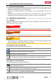
1 Information about the documentation 1.1 About this documentation • Read this documentation before initial operation or use. This is a prerequisite for safe, trouble-free handling and use of the product. • Observe the safety instructions and warnings in this documentation and on the product. • Always keep the operating instructions with the product and make sure that the operating instructions are with the product when it is given to other persons. 1.2 Explanation of symbols used 1.2.
This symbol is intended to draw special attention to certain points when handling the product. 1.3 Product-dependent symbols 1.3.
may present hazards when used incorrectly by untrained personnel or when used not as directed. The type designation and serial number are printed on the type identification plate. ▶ Write down the serial number in the table below. You will be required to state the product details when contacting Hilti Service or your local Hilti organization to inquire about the product. Product information → page 5 Product information Electric wall saw Generation Serial no. 1.
▶ Do not abuse the cord. Never use the cord to carry the tools or pull the plug from an outlet. Keep cord away from heat, oil, sharp edges or moving parts. Replace damaged cords immediately. Damaged cords increase the risk of electric shock. ▶ When operating a power tool outside, use an outdoor extension cord marked “W-A” or “W”. These cords are rated for outdoor use and reduce the risk of electric shock.
2.1.2 Basic safety instructions ▶ Use the machine only when it is in perfect working order. Check the machine, cables and plugs for damage each time before use. Have damaged parts repaired or replaced. If the cable is damaged or cut through during use, unplug the cable from the electric supply immediately. Contact Hilti Service. ▶ Follow all safety instructions and other instructions printed in the documentation or on the machine.
▶ Disconnect the power cable before beginning cleaning and maintenance work or in the event of an interruption between periods of operation. 2.1.4 Safety measures at the danger areas WARNING A risk is presented by moving parts, by falling objects or debris that may fly off. Falling objects could cause serious injury. ▶ Make sure that the area is cordoned off, that supports are in place and warnings to third parties are displayed.
▶ Never stand directly in line with the rotating saw blade. ▶ Safety measures must also be implemented in the area not directly visible to the operator, i.e. at the rear of objects being cut. ▶ Never loiter in a position directly below the equipment. 2.1.
▶ Do not operate the machine in explosive atmospheres, such as in the presence of flammable liquids, gases or dust. Electric tools and machines generate sparks which may ignite dust or vapors. ▶ Always lead cables and hoses flat on the ground or floor away from the machine. This will help to reduce the risk of tripping while working. ▶ Keep cables and hoses away from rotating parts. ▶ Make sure that the cooling water used is drained away or collected (vacuum) in a suitably controlled manner.
▶ Use the transport trolley only to transport the saw system and its specified accessories. Do not use the trolley to transport other items or materials. ▶ Before lifting, check that all removable items of equipment are securely attached to the transport trolley or locked in position. ▶ Avoid lifting and carrying heavy objects. Use suitable lifting equipment and means of transport and share heavy loads between several people. ▶ Use the grips provided for transportation.
3 Description 3.1 Product overview @ ; = % & 12 Saw head Remote control unit Transport trolley Lifting point for transport by crane Blade guard center section English Printed: 13.05.
3.2 Intended use The product described is a water-cooled, electrically powered wall saw with wireless remote control. It is designed for cutting lightly to heavily reinforced concrete as well as stone or masonry structures using diamond-tipped saw blades with a diameter of between 23.6 in (600 mm) and 63 in (1600 mm). The maximum permissible blade diameter for starting cuts is 31.5 in (800 mm). Diamond saw blades with a diameter of up to 47.
3.
Accessories for the flush-cutting blade guard Item number 238006 238007 238008 238009 256237 Designation DS-BGF80 middle section Description Saw blade guard for flush cutting, Ø 23.6 in … 35.4 in (600 mm … 900 mm) DS-BGF80 side section, set Saw blade guard for flush cutting, Ø 23.6 in … 35.4 in (600 mm … 900 mm) DS-BGF120 middle section Saw blade guard for flush cutting, Ø 39.4 in … 47.2 in (1,000 mm … 1,200 mm) DS-BGF120 side section, Saw blade guard for flush cutting, set Ø 39.4 in … 47.
Mains connection (phase requirements) Rated current AC supply fuse rating (depends on setting on the remote control unit) Generator power requirements Leakage current Permissible saw blade diameter Maximum blade diameter for guide cut Maximum cutting depth Weight Storage temperature Application temperature, ambient temperature Cooling water flow rate Cooling water temperature Cooling water pressure Protection class in accordance with IEC 60529 Maximum emitted transmission power (PEIRP) Frequency band 4.
220 lb (100 kg) 30 psi (2.1 bar) Weight, loaded Tyre pressure 5 Planning 5.1 Cutting sequence ▶ Make dividing cuts to adjust the maximum size and weight of the concrete blocks to the prevailing conditions (i.e. the lifting capacity of the crane or the maximum permissible floor loading capacity and size of doors). A rational cutting sequence can be followed when the rail supports are cleverly positioned at a suitable distance.
5.2 Overcut or uncut distances s 7.9 in (200 mm) 8.9 in (225 mm) 9.8 in (250 mm) 10.8 in (275 mm) 11.8 in (300 mm) 12.8 in (325 mm) 13.8 in (350 mm) 14.8 in (375 mm) 15.7 in (400 mm) 16.7 in (425 mm) 17.7 in (450 mm) 18 25.6 in (650 mm) 5.5 in (139 mm) 7.3 in (185 mm) 10.7 in (273 mm) English Printed: 13.05.2019 | Doc-Nr: PUB / 5355799 / 000 / 04 a with blade diameter (Ø) 31.5 in 39.4 in 47.2 in (800 mm) (1,000 mm) (1,200 mm) 3.9 in 3.0 in 2.4 in (100 mm) (75 mm) (61 mm) 5.0 in 3.7 in 2.
s 18.7 in (475 mm) 19.7 in (500 mm) 20.7 in (525 mm) 21.7 in (550 mm) 22.6 in (575 mm) 23.6 in (600 mm) 24.6 in (625 mm) 25.6 in (650 mm) 26.6 in (675 mm) 27.6 in (700 mm) 28.5 in (725 mm) 25.6 in (650 mm) a with blade diameter (Ø) 31.5 in 39.4 in 47.2 in (800 mm) (1,000 mm) (1,200 mm) 13.7 in (349 mm) 16.3 in (415 mm) 21.1 in (536 mm) 63.0 in (1,600 mm) 8.4 in (213 mm) 9.3 in (237 mm) 10.4 in (264 mm) 11.6 in (294 mm) 12.8 in (326 mm) 14.3 in (363 mm) 15.9 in (404 mm) 17.8 in (452 mm) 20.
5.4 @ ; = Position of holes drilled for fastening the rail supports Distance between anchors with rail support positioned on the inside = 9.3 in (235 mm) Distance between anchors with rail support positioned on the outside = 9.1 in (230 mm) Distance between rail supports with support positioned on the inside = 5.7 in (144 mm) % & ( Distance between rail supports with support positioned on the outside = 5.5 in (139 mm) Distance between anchors for flush-cutting = 10.
Technical data AC supply fuse rating (depends on setting on the remote control unit) Ground fault circuit interrupter (GFCI) • 16 A • 25 A • 32 A Type A, 30 mA Pin assignment 3~ + N + PE 5.6 X Phase 1 Y Phase 2 Z Phase 3 G Earth / ground conductor Use of extension cables WARNING A damaged supply cord presents a hazard! Do not touch the supply cord or extension cord if damaged while working. Disconnect the supply cord plug from the power outlet.
6 Assembling the saw system 6.1 Installing the anchors for the rail supports WARNING Inadequate fastening presents a hazard! A basic prerequisite for safe and efficient use of the saw system is that it must be secured using a means of fastening suitable for the applicable material and of adequate dimensions. ▶ Use a fastening system suitable for the material on which you are working and observe the fastening system manufacturer’s instructions.
6.3 @ ; = Mounting the rail on the rail supports for normal cutting Rail Rail clamp Rail support % & ( Rail clamping plate Rail clamping bolt Leveling screw 1. Fit rail hooks on the rail. Rail hooks may be used only together with rail supports for normal cutting. 2. Engage the rail with the rail hooks in the rail supports and slide the clamping plates over the edge of the rail. 3. Bring the rail supports into alignment at right angles to the rail and then tighten the rail clamping bolts. 4.
6.4 Mounting the rail on the rail supports for angular cutting and adjusting the cutting angle 1. Slacken the clamping bolt for the clamping plate on all rail supports. @ ; = % Leveling screw Clamping plate with clamping bolt Clamping bolt for angle adjustment Slot for the fastening bolt 2. Fit the rail onto the rail supports. 3. Slide the clamping plates over the edge of the rail and tighten the plate clamping bolts. 4. Unscrew the lower clamping bolt for the angle adjustment mechanism.
5. 6. 7. 8. 9. Remove the clamping bolt from the rail support. Slacken the upper clamping bolt for the angle adjustment mechanism. Adjust the rail to the desired cutting angle. Retighten the clamping bolt for the angle adjustment mechanism. Check and adjust the offset distance of the rail from the cutting line and then tighten the rail support fastening bolts. Dimensions for setting up for angular cutting → page 25 10.Use the leveling screws to compensate for differences in level. 11.
6.5 Mounting the rail on the rail supports for cutting on stairs 1. Mount the rail supports for cutting on stairs on the stairs. 2. Attach the clamping insert for cutting on stairs to the rail support. 3. Slacken the clamping bolts for angle adjustment.
6.6 @ ; = Extending rails Rail Tapered connector Eccentric pins % & 1/2" square pin wrench Tapered sleeve 1. Clean the tapered connector and tapered sleeves and then grease these parts. 2. Insert the tapered connector in the rail and tighten the eccentric pin by turning it in clockwise with the 1/2" square wrench. The rail extension can be removed by releasing the eccentric pin by turning it in counterclockwise and pushing out the tapered connector. 7 Preparing the saw system for use 7.
@ ; Locking lever Rail = Guide roller 1. Disengage the locking lever by lifting and pivoting the lever upwards. ➥ Spring pressure holds the locking lever in the “open” position. 2. Lift the saw head by the grips and place it on the previously fastened rail. Make sure that the guide rollers are positioned correctly. ➥ The guiding surface of the rail should lie against the middle of the guide rollers. 3. Lift the locking lever slightly and pivot it back to the casing edge. 4.
7.1.1 Installing the rail and flush-cutting saw head ▶ When installing, make sure that the saw blade does not come into contact with the material, as otherwise friction losses would reduce the saw's performance. ▶ Allow approx. 5 mm of extra clearance between saw blade and material, or use the leveling screws rail support to set the saw to a slight angle. @ ; 7.2 @ ; = % 183 mm (7.2 in) 274 mm (10.
WARNING Risk of unintentional starting! The saw could start unintentionally when the electric supply cable is plugged in. ▶ Press the emergency stop button on the remote control unit before connecting the electric supply cable. CAUTION Risk of accident! Incorrectly positioned cables and hoses can result in damage to the equipment or other property. ▶ Position the cables and hoses so that they can follow the movement of the saw head without being under tension.
4. Move the lever further, beyond the pressure point. ➥ The blade guard holder is then fixed in the set position. To release the blade guard holder, move the lever in the opposite direction. 7.4 Mounting the saw blade 7.4.1 General information on installing saw blades ▶ Thoroughly clean the mounting flange before installing the blade. ▶ Clean and degrease the clamping surfaces on the saw blade, on the blade mount and on the clamping flange before mounting the saw blade.
7.4.3 Mounting the saw blade for flush cutting 7.4.3.1 Preparing the flush-cutting flange for installation @ ; = % Hex key Flush-cutting flange, complete Locking pin Outer ring & ( ) Securing screws (hex socket, 6 mm) Saw-blade flange Inner flange 1. Use the hex key to press the locking pin into the flush-cutting flange and turn the outer ring in the direction shown until the locking pin engages in the 2nd hole in the outer ring. ➥ The outer ring moves aside, exposing 2 securing screws. 2.
5. Tighten the securing screw. Technical data Tightening torque, inner-flange securing screw (M12×45 10.9) 81 ftlbf (110 Nm) 7.4.3.3 Installing the saw-blade flange of the flush-cutting flange on the saw blade 1. Remove the saw blade securing screws from the saw-blade flange. 2. Lubricate the 6 mounting bolts lightly with oil. @ ; Saw blade Saw-blade flange = % Fastening screws Mark (position of the short securing screw) 3.
Saw blades with saw-blade flange for flush-cuts installed can be easily carried with the carrying handle supplied for the purpose. Consequently, it is a good idea to install saw-blade flanges on the saw blades needed. Additional saw-blade flanges are available separately. Installing the carrying handle ▶ Position the saw blade with the opening in the saw-blade flange facing down. ▶ Guide the plate on the carrying handle from below into the recess in the saw-blade flange.
@ ; = % Saw arm Inner flange Saw-blade flange Hex key & ( ) + Fastening screws Outer ring on inner flange Locking pin Lever, keyless locking system 1. Position the saw blade so that the mount on the saw blade is at a right angle to the rail. 2. Remove the carrying handle from the saw-blade flange and thoroughly clean the mount on the inner flange and the saw-blade flange. 3.
4. Turn the inner flange until the screws in the inner flange point toward the mount on the saw-blade flange. 5. Pivot the saw arm up. ➥ The mount on the inner flange is guided into the mount on the saw-blade flange. 6. Tighten the two securing screws in the clockwise direction. Technical data Mounting bolt tightening torque 15 ftlbf (20 Nm) Materials 6 mm hex key 7.
4. Pivot the saw arm toward the rail. Hold the saw blade so that it cannot topple or drop out when released. ➥ The inner flange on the saw arm disengages from the mount on the saw-blade flange. ➥ The saw blade is now completely disengaged from the saw and can be carried away with the carrying handle. 7.
3. Secure the blade guard side section with the tensioning bar. ➥ The blade guard middle section and side section then form a unit that can be removed or refitted to the blade guard holder as a single unit. 4. Secure the complete blade guard to the blade guard holder by pulling the rubber tensioning strap over the tensioning lug. ➥ The blade guard is then ready for use.
8.2 Guidelines and guide values The initial or guide cut The initial cut is known as the guide cut. This cut should always be made with the saw arm in the trailing position (i.e. pulling the blade). The depth of the cut depends on the material (hard, soft or masonry). Technical data Cutting depth for the guide cut ≈ 2 in (≈ 4 cm) ▶ When making the guide cut, the power of the saw should be reduced in order to ensure a straight cut.
4. Disconnect the remote control unit from the saw head and fit the protective caps to the connectors / sockets. If the remote control unit is used without a cable: Switch the remote control unit off. 5. Remove the blade guard from the saw blade. 6. Disconnect the cooling water hose from the saw head. 7. Blow out the cooling circuit. → page 40 CAUTION Risk of injury! A hot saw blade presents a risk of burning injury. Sharp edges present a risk of cutting injury.
10 Care and maintenance WARNING Electric shock hazard! Attempting care and maintenance with the supply cord connected to a power outlet can lead to severe injury and burns. ▶ Always unplug the supply cord before carrying out care and maintenance tasks. WARNING Risk of personal injury and damage to the equipment or other property! Water finding its way into the saw may result in damage to the saw and increase the risk of electric shock.
4. Retighten the clamping screw. It must be possible to turn the guide roller by hand. 5. Adjust the second roller in the same way. 10.2 Inspection ▶ Have the machine checked by Hilti Service at intervals of 200 operating hours. The remote control unit shows the number of operating hours remaining until the next service is due. ▶ Check all visible parts and controls for signs of damage at regular intervals and make sure that they all function correctly. 10.
Parts Blade guard Saw head Mounting flange Cables / plugs Transport trolley Tool set 11 Procedure Check the clamping lever tension and adjust if necessary by turning the hex. head bolt. Check the locking mechanism for ease of operation and secure locking. Clean, lubricate (grease nipples) or have repaired if necessary. Check the guide rollers for ease of operation and excessive play, have them replaced / repaired as necessary.
Trouble or fault The cut is not straight. Low sawing performance. 44 English Printed: 13.05.2019 | Doc-Nr: PUB / 5355799 / 000 / 04 Possible cause The saw blade is blunt. Action to be taken ▶ Change the saw blade. Pay attention to the specification. No guide cut made or the ▶ Check whether the given guide cut was not straight guide values were adhered to. The play at the guide rollers ▶ Check the play at the exceeds the specified value. rollers and adjust the rollers correctly.
Trouble or fault The saw blade is jammed in the kerf and the saw doesn’t start. Possible cause A piece of steel cut free is jammed in the kerf. The part cut free is pressing against the saw blade. 13 Action to be taken ▶ Try to lift the saw blade out of the kerf by alternately moving the saw head forward and back (advance / return). Try to start the blade drive as soon as the blade can be moved freely. Caution! Avoid use of excessive force as this could result in damage.
15 FCC statement (applicable in US) / IC statement (applicable in Canada) This device complies with Part 15 of the FCC Rules and RSS-210 of lC. Operation is subject to the following two conditions: 1. this device may not cause harmful interference, and 2. this device must accept any interference received, including interference that may cause undesired operation. 46 English Printed: 13.05.
Printed: 13.05.
*2122329* 2122329 Hilti = registered trademark of Hilti Corp., Schaan Printed: 13.05.