
Product Technical Guide for MQK Brackets

Hilti MI/MQ Technical Guide
4.2 MQ System Components — Load Data and Material Specications
Hilti, Inc. (US) 1-800-879-8000 | www.us.hilti.com I en español 1-800-879-5000 I Hilti (Canada) Corp. 1-800-363-4458 I www.hilti.ca I MI/MQ Technical Guide 2015
89
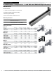
Technical Data — Section Properties
MQK Brackets 21 (13/16") 41 (1-5/8") 41/3 (1-5/8") 72 (1-7/8") 21 D (13/16 B2B) 41 D (1-5/8" B2B)
Thickness 14 ga 2.00 mm 14 ga 2.00 mm 11 ga 3.00 mm 12 ga 2.75 mm 14 ga 2.00 mm 14 ga 2.00 mm
Profile Weight 0.968 lb/ft 1.44 kg/m 1.398 lb/ft 2.08 kg/m 1.955 lb/ft 2.91 kg/m 2.755 lb/ft 4.10 kg/m 2.002 lb/ft 2.98 kg/m 2.883 lb/ft 4.29 kg/m
Area of section 0.256 in
2
1.65 cm
2
0.380 in
2
2.45 cm
2
0.540 in
2
3.48 cm
2
0.764 in
2
4.93 cm
2
0.512 in
2
3.31 cm
2
0.760 in
2
4.90 cm
2
Moment of inertia Ix 0.022 in
4
0.92 cm
4
0.129 in
4
5.37 cm
4
0.169 in
4
7.02 cm
4
0.690 in
4
28.70 cm
4
0.120 in
4
4.98 cm
4
0.737 in
4
30.69 cm
4
Moment of inertia Iy 0.105 in
4
4.39 cm
4
0.176 in
4
7.33 cm
4
0.251 in
4
10.44 cm
4
0.370 in
4
15.40 cm
4
0.211 in
4
8.78 cm
4
0.352 in
4
14.67 cm
4
Section Modulus Sx 0.052 in
3
0.85 cm
3
0.155 in
3
2.54 cm
3
0.199 in
3
3.26 cm
3
0.476 in
3
7.80 cm
3
0.148 in
3
2.42 cm
3
0.453 in
3
7.43 cm
3
Section Modulus Sy 0.130 in
3
2.13 cm
3
0.217 in
3
3.55 cm
3
0.309 in
3
5.06 cm
3
0.455 in
3
7.46 cm
3
0.259 in
3
4.25 cm
3
0.433 in
3
7.10 cm
3
Radius of Gyration Rx 0.291 in 0.74 cm 0.583 in 1.48 cm 0.559 in 1.42 cm 0.949 in 2.41 cm 0.484 in 1.23 cm 0.984 in 2.50 cm
Radius of Gyration Ry 0.642 in 1.63 cm 0.681 in 1.73 cm 0.681 in 1.73 cm 0.697 in 1.77 cm 0.642 in 1.63 cm 0.681 in 1.73 cm
Gravity Axis e1 0.427 in 1.08 cm 0.832 in 2.11 cm 0.847 in 2.15 cm 1.448 in 3.68 cm 0.811 in 2.06 cm 1.626 in 4.13 cm
Gravity Axis e2 0.384 in 0.98 cm 0.794 in 2.02 cm 0.779 in 1.98 cm 1.387 in 3.52 cm 0.811 in 2.06 cm 1.626 in 4.13 cm
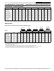
Bracket
F1 F1 F1 F2 F3
L (in.) L (mm)
lb N lb N lb N lb N lb N
MQK-21/300
11-13/16 300 128 570 128 570 63 280 63 280 43 190
MQK-21/450
17-11/16 450
85 380 85 380 40 180 43 190 27 120
MQK-41/600 23-5/8
600
189
840
189
840
94 420 94 420 63 280
MQK-41/3/300 11-13/16 300 382 1700 382 1700 191 850 191 850 126 560
MQK-41/3/600 23-5/8 600 187 830 187 830 92 410 92 410 61 270
MQK-72/600 23-5/8 600 454 2020 454 2020 227 1010 227 1010 151 670
MQK-21 D/600 23-5/8 600 175 780 175 780 88 390 88 390 58 260
MQK-41 D/750 29-1/2 750 360 1600 360 1600 180 800 180 800 119 530
MQK-41 D/1000
39-3/8 1000 265 1180 265 1180 133 590 133 590 88 390
• Loading capacity of bracket fastened to concrete with KB-TZ 1/2" x 3-3/4" (with an embedment depth of 3"using ASD allowable load values) or KH-EZ 1/2" x 4".
• The deection of L/150 was observed at the point of load application.
• The loads apply only when strut opening pointing upwards or downwards.
• The bracket’s own weight has been accounted for.
• Concrete strength minimum 3000 psi.
• Fastener loads based on no edge distance or anchor spacing effects. Reference Vol. 2 Hilti Anchoring Technical Guide for details.
• Engineer of record is responsible for verifying suitability of the components, connection, anchor selection and base material for any specic application.
• The application guidelines applicable to the anchor must be observed.Reference Vol. 2 Hilti Anchoring Technical Guide.
• Load values for steel are based on the lesser of allowable stress, 25,000 psi, or a deection limit of L/150 at the outer most loading point.
F1 = w x L
F1
1/2 1/2
F1
F2 F2
1/3 1/3 1/3
F3 F3 F3
1/4 1/4 1/4 1/4
Technical Data — Allowable Loads for Carbon and Stainless Steels
MQK Brackets