
Operating Instruction AG 500-12D (04)
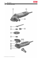
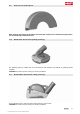
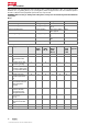
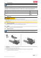
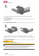
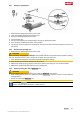
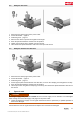
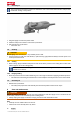
Table Of Contents
- Original operating instructions
- 1 Information about the documentation
- 2 Safety
- 3 Description
- 3.1 Overview of the product
- 3.2 Intended use
- 3.3 Items supplied
- 3.4 Starting current limiter
- 3.5 Constant-speed electronics
- 3.6 Active Torque Control (ATC)
- 3.7 Restart interlock
- 3.8 Temperature-dependent motor protection
- 3.9 Front cover for the disc guard
- 3.10 DG-EX 125/5 dust hood for grinding (accessory)
- 3.11 DC-EX 125/5C dust hood for cutting (accessory)
- 4 Consumables
- 5 Technical data
- 6 Before use
- 7 Types of work
- 8 Care and maintenance
- 9 Transport and storage
- 10 Troubleshooting
- 11 Disposal
- 12 Manufacturer’s warranty

English 13
5 Technical data
For rated voltage, rated current, frequency and/or input power, refer to the country-specific type
identification plate.
If the device is powered by a generator or transformer, the generator or transformer’s power output must be
at least twice the rated input power shown on the rating plate of the device. The operating voltage of the
transformer or generator must always be within +5 % and -15 % of the rated voltage of the device.
AG 500-12D
Maximum disc diameter
5 in
Drive spindle thread
5/8"-11
Weight
5.7 lb
(2.6 kg)
6 Before use
CAUTION
Risk of injury. The accessory tool may be hot or have sharp edges.
▶ Wear protective gloves when fitting, removing or adjusting the accessory tool or other parts and when
troubleshooting.
6.1 Fitting the side handle
▶ Screw the side handle into one of the threaded bushings provided.
6.2 Guard
▶ Observe the instructions for fitting the applicable guard.
6.2.1 Installing the guard
The guard is keyed to ensure that only guards of a type suitable for use with the product can be
installed. The keyed locating lug also prevents the guard from coming into contact with the tool.
1. Fit the guard on to the arbor collar so that the two triangular marks on the guard and on the product are
in alignment.
2. Press the guard on to the drive spindle collar.
3. Press the guard release button and turn the guard until it engages in the desired position.
◁ The guard release button jumps back.
Printed: 20.04.2018 | Doc-Nr: PUB / 5300555 / 000 / 01