
Installation Sheet


start here
commencez ici
empezar aquí
Assembly Instructions
Item No: 1167
LV
Les Instructions D’assemblage
Numéro d’article: 1167
LV
Instrucciones De Montaje
Número del artículo: 1167
LV
English Spanish
French
1. Find a clear area in which you can work.
2. Unpack fixture and glass from carton.
3. Carefully review instructions prior to assembly.
1. Encontrar un área clara en la que se puede trabajar.
2. Desembale luminaria y el vidrio de la caja.
3. Revise cuidadosamente las instrucciones antes del montaje.
1. Trouvez un endroit clair dans lequel vous pouvez travailler.
2. Déballez luminaire et de verre du carton.
3. Examinez attentivement les instructions avant l'assemblage.
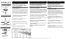
DRAWING 1 - ROOF ASSEMBLY
DRAWING 2 - GLASS INSTALLATION
1
2
G
N
3
T
H
6
4
5
DRAWING 3 - MOUNTING FIXTURE
1. To begin glass installation it will be necessary to remove the roof (2). This is accom-
plished by removing the four screws (1) from under the roof lip, and then lifting off the roof.
Set screws aside in a safe place for use later- see Drawing 1.
2. To install glass (3) align notches (N) in bottom of glass lip with offset in glass fitter (G),
and slip glass down into fitter. Then turn glass clockwise to lock glass in place
- see Drawing 2.
NOTE: fixture should be lamped prior to installing the glass.
3. To attach bracket (4) to roof, align holes in bracket tab (T) with two holes (H) in the roof.
Use barrel knob with stud (5) and slip it through hole roof from the inside. Then use knob
(6) and thread it onto the end of stud to secure bracket to roof - see Drawing 2.
1. Para comenzar la instalación del vidrio, será necesario quitar el techo (2). Esto
se logra quitando los cuatro tornillos (1) de debajo del borde del techo y luego
levantando el techo. Coloque los tornillos a un lado en un lugar seguro para su
uso posterior; consulte el Dibujo 1.
2. Para instalar el vidrio (3) alinee las muescas (N) en la parte inferior del borde
del vidrio con la compensación en el ajustador de vidrio (G), y deslice el vidrio
hacia abajo en el ajustador. Luego gire el vidrio en el sentido de las agujas del
reloj para bloquear el vidrio en su lugar - vea el Dibujo 2.
NOTA: el artefacto debe sellarse antes de instalar el vidrio.
3. Para fijar el soporte (4) al techo, alinee los agujeros en la pestaña del soporte
(T) con dos orificios (H) en el techo. Use la perilla del barril con el perno (5) y
deslícela a través del techo del orificio desde el interior. Luego use la perilla (6) y
enrósquela en el extremo del perno para asegurar el soporte al techo - vea el
Dibujo 2.
1. Pour commencer l'installation du verre, il sera nécessaire d'enlever le toit (2). Ceci
est accompli en enlevant les quatre vis (1) sous la lèvre du toit, puis en soulevant le
toit. Mettre les vis de côté dans un endroit sûr pour une utilisation ultérieure - voir le
dessin 1.
2. Pour installer la vitre (3), aligner les encoches (N) dans la partie inférieure de la
lèvre en verre avec le déport en verre (G) et glisser la vitre dans l'ajusteur. Tournez
ensuite la vitre dans le sens des aiguilles d'une montre pour verrouiller la vitre en
place - voir dessin 2.
REMARQUE: le luminaire doit être éclairé avant d'installer la vitre.
3. Pour fixer le support (4) au toit, aligner les trous de la patte du support (T) avec
deux trous (H) dans le toit. Utilisez le bouton de barillet avec le goujon (5) et
glissez-le à travers le toit du trou de l'intérieur. Ensuite, utilisez le bouton (6) et
enfilez-le sur l'extrémité du goujon pour fixer le support au toit - voir dessin 2.
MOUNTING INSTRUCTIONS
1. Your fixture is supplied with a mounting bracket that can be attached to a junction box or
any other type of surface material. The mounting bracket (A) has various holes which can
be used for mounting the fixture - see DRAWING 3.
PLEASE NOTE: IT IS THE RESPONSIBILITY OF THE PRUCHASER TO USE
THE APPROPRIATE MOUNTING HARDWARE FOR YOUR PERTICULAR
INSTALLATION.
2. To access the mounting bracket. You will first have to remove the four screws (B) on
base. After these screws are removed, please put them in a safe place for use later in the
installation process. The mounting plate can now be reomoved from the fixture base.
3. Now attach the mounting plate to the mounting surface using appropriate mounting
fasteners for your perticular mounting needs.
PLEASE MAKE SURE THE MOUNTING BRACKET IS ORIENTED CORRECTLY SO
THE FIXTURE IN THE CORRECT POSITION WHEN IT IS ATTACHED TO THE MOUNT-
ING BRACKET.
4. After mounting bracket is installed please wire fixture following instruction sheet ISLV
provided.
5. To finish installation, slip bottom of fixture over the mounting bracket and align screw
holes with threaded holes on side of base. Now thread in screws removed earlier and
tighten to complete installation and follow instructions on instruction sheet IS200 provided.
1. Su accesorio se suministra con un soporte de montaje que se puede acoplar a
una caja de conexiones o cualquier otro tipo de material de superficie. El soporte
de montaje (A) tiene varios orificios que se pueden usar para montar el dispositi-
vo; consulte DIBUJO 3.
TENGA EN CUENTA: ES RESPONSABILIDAD DEL PRUCHASER UTILIZAR
EL HARDWARE DE MONTAJE APROPIADO PARA SU INSTALACIÓN PERTÍ-
TAS.
2. Para acceder al soporte de montaje. Primero tendrá que quitar los cuatro
tornillos (B) en la base. Después de retirar estos tornillos, colóquelos en un lugar
seguro para usarlos más adelante en el proceso de instalación. La placa de
montaje ahora se puede cambiar desde la base del accesorio.
3. Ahora conecte la placa de montaje a la superficie de montaje usando los
sujetadores de montaje apropiados para sus necesidades de montaje especial.
POR FAVOR, ASEGÚRESE DE QUE EL SOPORTE DE MONTAJE ESTÉ
ORIENTADO CORRECTAMENTE PARA QUE EL ARTEFACTO EN LA POSICIÓN
CORRECTA CUANDO SE FIJE AL SOPORTE DE MONTAJE.
4. Después de instalar el soporte de montaje, coloque el accesorio de alambre
siguiendo la hoja de instrucciones ISLV incluida.
5. Para finalizar la instalación, deslice la parte inferior del accesorio sobre el
soporte de montaje y alinee los orificios para tornillos con los orificios roscados en
el costado de la base. Ahora enrosque los tornillos retirados anteriormente y
apriételos para completar la instalación y siga las instrucciones en la hoja de
instrucciones IS200 provista.
1. Votre appareil est fourni avec un support de montage qui peut être fixé à une
boîte de jonction ou à tout autre type de matériau de surface. Le support de
montage (A) comporte divers trous pouvant être utilisés pour le montage de
l'appareil - voir SCHÉMA 3.
S'IL VOUS PLAÎT NOTE: IL EST DE LA RESPONSABILITÉ DU PRUCHASER
D'UTILISER LE MATÉRIEL DE MONTAGE APPROPRIÉ POUR VOTRE INSTALLA-
TION PERTICULAIRE.
2. Pour accéder au support de montage. Vous devrez d'abord retirer les quatre vis
(B) sur la base. Après avoir retiré ces vis, veuillez les mettre dans un endroit sûr
pour les utiliser plus tard dans le processus d'installation. La plaque de montage
peut maintenant être retirée de la base de l'appareil.
3. Fixez maintenant la plaque de montage à la surface de montage en utilisant les
fixations de montage appropriées pour vos besoins de montage.
VEUILLEZ S'ASSURER QUE LE SUPPORT DE MONTAGE EST CORRECTE-
MENT ORIENTÉ, DE SORTE QUE L'APPAREIL SOIT DANS LA POSITION
CORRECTE LORSQU'IL EST ATTACHÉ AU SUPPORT DE MONTAGE.
4. Une fois le support de montage installé, veuillez fixer le luminaire en suivant la
feuille d'instructions ISLV fournie.
5. Pour terminer l'installation, glisser le bas de l'appareil sur le support de montage
et aligner les trous de vis avec les trous filetés sur le côté de la base. Enfilez
maintenant les vis retirées plus tôt et serrez pour terminer l'installation et suivez les
instructions sur la feuille d'instructions IS200 fournie.
A
B
MOUNTING SURFACE
INSTRUCCIONES DE MONTAJE
INSTRUCTIONS DE MONTAGE
HH
II
NN
KK
LL
EE
YY
HINKLEY 33000 Pin Oak Parkway, Avon Lake, OH 44012 800.446.5539 / 440.653.5500 hinkley.com
FOR WIRING WITH LOW VOLTAGE LAMPS TO A
TRANSFORMER PLEASE REFER TO I.S. LV
PARA EL CABLEADO CON LUCES DE BAJA
TENSION A UN TRANSFORMADOR, CONSULTE
I.I.S.
POUR LE CÂBLAGE AVEC DES LAMPES BASSE
TENSION À UN TRANSFORMATEUR, VEUILLEZ
VOUS RÉFÉRER À I.S. LV