
User manual
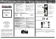


Kontrollrelais / Monitoring-relay –
in-
case – Füllstandsüberwachung / Liquid level monitoring – ICL
Copyright © 2008 by HIQUEL GmbH, Bairisch Kölldorf 266, 8344 Bad Gleichenberg, AUSTRIA. Alle Rechte vorbehalten, All rights reserved. 5
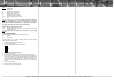
Legend:
U Supply voltage
Y Liquid level
S1 Position sensor 1 („Fill/Empty“)
S2 Position sensor 2 („Fill/Empty“)
S3 Position sensor 3 („Alarm“)
te On-delay time relay 1 „Fill/Empty“
tr Off-delay time relay 1 „Fill/Empty“
tr+te AL On- and off-delay time relay 2 „Alarm“
t Time
Note:
It is not necessary to remove the supply voltage before making any
changes in the setting of the controls. If either threshold or function is
changed the red LED-indicator F is active for a short time for checking pur-
poses. The new settings are immediately active. Depending on the change of
the settings, the output relay might be switched off temporary.
OUTPUT RELAY 1 “Fill/Empty” and 2 “Alarm”
Active Condition depends on the function.
Inactive Condition depends on the function or the device has an internal fault
(see LED-indicator F).
Note:
The output relays are galvanically isolated from the power supply
terminals!
SPECIAL OPERATING MODES
The following special operating modes are available for the ICL:
#2 Volatile
#4 Non-volatile
The factory setting is „#2 - Volatile“. To switch between the special operating
modes consider the following steps:
1. Write down the actual DIP-switch settings
2. Turn off the power supply
3. Change the DIP-switch positions as shown below:
4. Press the MR-button and keep pressed!
5. Turn on the power supply
6. As soon as the LED-indicator F flashes, the MR-button can be released
7. Every stroke on the MR-button changes the special operating mode. The
actual mode is indicated with a special flashlight signal on the LED-indicator
F. The flash signal is composed as follows: Number of operating mode =
number of flashlight signals followed by a short pause. This signal is re-
peated constantly. The last-selected special function mode is automatically
stored.
8. Turn off the power supply
9. Restore the original DIP-switch settings
10. The device can be put in operation again