
Manual


Hired-Hand Mfg., Inc. • 1733 Co Rd 68 • Bremen, Alabama 35033 • Phone 256-287-1000 • Fax 256-287-2000
Part No. 4801-3041 Rev 03-09A
CAUTION! Be sure that heater is cool before touching internal surfaces. These surfaces
remain hot enough to cause severe burns during and after operation.
TOOLS REQUIRED:
1/4” Nut Driver Cordless Drill 11/32” Wrench
7/16” Nut Driver 3/16” Drill Bit 1/2” Wrench
Flat Head Screwdriver 1/2" Drill Bit 15mm Wrench
Phillips Head Screwdriver Pliers
MATERIALS REQUIRED: 6450-2121 KIT Con HSI to DSI 34” Canopy BJBrooder
6450-2122 KIT Con HSI to DSI 48” Canopy BJBrooder
Directions:
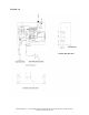
Step 1. Replace the components in the Control Module ( Figure 1.0 )
1. Open the control enclosure. Remove the brown wire coming from the igniter from the enclosure. Also
unplug the orange wire coming from the igniter and remove it from the enclosure.
2. Drill a 1/2” hole 2” to the right from the existing flame probe / igniter wire entrance.
3. Drill two 3/16” holes for the Direct Spark Igniter Module mount in the side next to the control module.
These holes will be 1” from the corner, 3/4" down from the top and 3 1/8” apart. (Use the DSI Module as
a guide for this if needed.)
4. Mount the DIRECT SPARK IGNITER MODULE (3591-2361) to the control box interior with two
#8x1/2” screws (1004-6029) and two nuts (1001-2597) in the newly drilled holes.
5. Remove the 1/2” nut from the fitting supplied on the new SPARK WIRE. Route the spark wire through
the 1/2” hole drilled earlier. Slip the 1/2" nut back on the spark wire and connect the wire to the Direct
Spark Igniter Module.
6. Slip the fitting on the spark wire into the 1/2" hole and secure it with the 1/2" nut that is on the wire.
7. Route the BLACK (1901-0096) wire from the DSI Module to the orange wire coming from the module and
connect them.
8. Connect the BROWN (0901-0171) wire to the terminal block where the previous brown wire was located
and route it to the DSI Module.
9. Connect the GREEN (0901-1263) wire at the terminal block where the other green ground wires are
located and route it to the DSI Module.
HSI to Direct Spark Igniter Kit
120V Bunsen Jet HSI Brooders
!
WARNING!
Disconnect All Electrical Power Sources and Shut Off Gas Supply Before
Beginning Change Out of the Igniter and Control Module Components