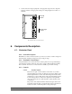
Contactor Control Systems 4, 8, or 12 Stage Contactor Panel with Back Up System Hired Hand, Inc.
Contactor Control Systems Table of Contents 1. Purpose ______________________________________________________________1 2. Ratings/Specifications __________________________________________________1 3. Warnings ____________________________________________________________1 4. Limited Warranty ______________________________________________________2 5. Installation ___________________________________________________________2 5.1. Tools Required ____________________________________________________________ 2 5.2.
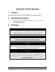
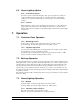
Contactor Control Systems 1. Purpose Contactor Control Systems allow an electronic temperature controller to stage in equipment in predetermined increments. The contactor panel is intended for use in agricultural enclosures. 2. Ratings/Specifications • • • 3. 120 or 240 volts / 6 Amps Maximum / 50/60 hertz (depending on model purchased). 2 hp maximum per stage. 4, 8, or 12 stage models available.
. Limited Warranty All products are warranted to be free from defects in material and workmanship for a period of one year from the date of purchase if installed and used in strict accordance with the installation instructions. Liability is limited to the sale price of any products proved to be defective or, at manufacturers option, to the replacement of such products upon their return.
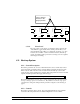
9. Connect wires from staged equipment to the appropriate stage. Be sure to align the heat/cool switches to the appropriate settings. See wiring diagrams for locations of terminals. Back-Up System ! ! M a n u a l Stage Controls The CCS-8 Contactor Control Panel. 6. Components Description 6.1. Contactor Panel 6.1.1. General Description Hired Hand’s Contactor Control System is a pre-wired set of heavy contactors designed to allow automatic switching of large loads. (Up to 2 Hp per stage.) 6.1.2.
These switches must be in the proper position. Copyright C 1991,1992 PCB 115 (REV 0) C O O L H E A T VR2 SW3 CR3 RLY3 August 26, 1991 L.Self C O O L VR3 H E A T SW4 CR4 C O O L VR4 J4 COOL RLY4 J5 6.1.3.2. Front Panel The only controls on the outside of a standard contactor panel are the “Auto/Off/On” toggle switches.
6.2.2.1. High Limit If for some reason (lightning, voltage fluctuations, etc.) your controller should quit functioning, or function improperly, the back-up system in your CCS panel will turn stages on or off if temperature exceeds the high or low limits. If the temperature felt by the sensor reaches one degree above the high limit, the backup board would start all stages set to cool one. (This could be any, or all of your cool stages.
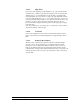
Wiring Diagram for Two Stage Cool Back-Up R HIRED-HAND AC - + SENSOR COOL HEAT GND STAGE COOL 2 1 COOL 1 STAGE HEAT 2 ALARM + - STAGE 3 STAGE This board found on back of CCS Panel door. 4 COOL HEAT GND Œ • COOL HEAT GND STAGE 5 When the back-up is wired in this manner, and the switches are aligned as shown, stages 3 and 4 would come on when the back-up board calls for Cool 1. STAGE When the back-up board calls for Cool 2 the remaining cool stages would start.
6.3. House Lighting Option 6.3.1. General Description On contactor panels ordered with the light control option, the panel has a double pole contactor installed inside the panel at the top of the unit. To the left of the lighting contactor is a four-position terminal strip. You can break up to two circuits with this contactor. 6.3.2.
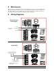
8. Maintenance There are few items on the CCS panel which require maintenance. This does not mean that maintenance is unimportant. Remember that the more time you spend making things right, the less time you will spend correcting problems. To prevent malfunctions of the contactor panel, keep your panel clean and free of debris. Follow all safety warnings when working with electrical equipment.
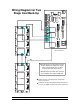
From Controller Lighting Circuit Two Circuits From Breaker Panel Out Circuit 1 Neutral Hot GROUND LIGHTS OUT LIGHT 2 IN 120VAC NEUT OUT COMMON IN FAN CONTROL MICRO SWITCH IN OUT Stage 1 5 9 IN OUT Stage 2 6 10 IN Stage L1 L2 L1 L2 L1 L2 L1 L2 L1 L2 Use one line from each of the two circuits. In LIGHT 1 House Lights 120VAC HOT Circuit 2 Neutral Hot P/N 3580-0131 Connecting Sensor to Back-Up Board R HIRED-HAND J1 ZNR1 VR1 ZNR2 AC BR1 C1 C2 c 1994,1995 Hired Hand, Inc.
Contactor Control Systems OUT Stage 3 7 11 IN OUT Stage 4 8 12 IN OUT Stage 1 5 9 IN OUT Stage 2 6 10 IN OUT Stage 3 7 11 IN OUT IN All wiring must meet N.E.C. and all Local Standards. IN Heater 120V/240V Stage 2 6 10 240 VAC Line 1 240 VAC Line 2 OUT Ground IN Note: When using a single pole contactor, only line 2 of the 120 Volt supply to the stage is broken by the contactor.
Contactor Control Systems IN OUT Stage 3 7 11 IN OUT Stage 4 8 12 IN OUT Stage 1 5 9 IN OUT Stage 2 6 10 IN OUT Stage 3 7 11 IN OUT IN All wiring must meet N.E.C. and all Local Standards. Stage 2 6 10 Fan 120V/240V OUT Ground 240 VAC Line 1 240 VAC Line 2 IN Note: When using a single pole contactor, only line 2 of the 120 Volt supply to the stage is broken by the contactor.
OUT Neutral OUT Stage 2 6 10 Stage 4, 8, 12 IN Stage IN OUT OUT LIGHT 2 IN LIGHTS IN IN LIGHT 1 GROUND Stage 3, 7, 11 Stage 1 5 9 Stage 2, 6, 10 L1 L2 L1 L2 L1 L2 L1 L2 L1 L2 COMMON IN OUT Stage 1 5 9 IN OUT Stage 2 6 10 Stage 1-4 IN OUT Stage 3 7 11 IN OUT Stage 4 8 12 L1 L2 L1 L2 L1 L2 L1 L2 L1 L2 L1 L2 L1 L2 L1 L2 IN OUT Stage 1 5 9 Stage 5-8 IN OUT Stage 2 6 10 IN OUT Stage 3 7 11 IN OUT Stage 4 8 12 L1 L2 L1 L2 L1 L2 L1 L2 L1 L2 L1 L2 L1 L2 L1 L2 IN OUT Stage
10. Troubleshooting Warning! WARNING! Electric Shock Hazard. These tests must only be run by a qualified technician. 10.1. A Stage not working correctly 1. 2. 3. 4. 5. Check and make sure that the controller is calling for stages to be on by observing the display. Make sure that the switch on the contactor panel is not in the off position. Make sure that the stages power is on in the breaker panel.
11.
Ref Chart D Power Supply section of 24 volt model Ref Chart B Ref Chart D Power Supply with House Lighting Option Contactor Control Systems 15
1039-2031 Ref Chart A 3001-2864 Part No. 1018-0104 1039-2031 1040-2518 3001-2864 3551-0101 6404-1191 6407-2593 Description STND_OFF LCBSB-10-01A-RT KNOB 1" dia 1/4 shft indctr LATCH Panel (CCS) SWTCH SPDT togle cen off tab BUZZER Pnl piezo 24VDC 1-1/8" /PCB131 after QA /Temperature sensor assy Part No.
Part No.