
Installation User Manual

HIRED-HAND, INC. · 1733 Co Rd 68 · Bremen, AL 35033 · Phone 1-800-642-0123 · Fax 205-287-2000
Part no. 4801-1209
Filter Kit Installation
Alert Alarm
tm
Part No. 4801-1209
Tools Required
Screwdriver
Directions
This kit includes this wiring diagram, and four diode assemblies like the one shown below.
1. Turn power switch to “OFF” and unplug Alert Alarm.
2. Open enclosure, and find the terminal strip.
3. Find the wiring for Sensor 1.
4. Loosen the wires for Sensor 1 from the terminal block. (Positions labeled “Sen 1”.)
5. Place one of the diode assemblies on the terminals along with the sensor wiring.(See
below for example.) Be sure that the Connector labeled “Signal” is attached to the
terminal labeled “sig”.
Warning!!!
Do not connect the diode assembly backwards.
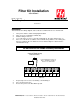
Siren Sen 1 Sen 2 Aux 1 Aux 2
red
wht
sig
gnd
sig
gnd
sig
gnd
sig
gnd
Signal
Connect wiring for Sensor 2,
Aux 1, and Aux 2 exactly as
Sensor 1 is shown here.
Connect Diode on top
of Sensor wires.
PCB 107
1. Repeat steps 3-6 for Sensor 2, Auxiliary 1, and Auxiliary 2.
2. Close electrical enclosure.
3. Restore the power to the Alert Alarm System.