Farm Hand Back Up System Temperature Controller Hired Hand, Inc.
Ratings and specifications • • • • 115/230 Volts (Depending on switch position.) 50/60 Hz. 12 Amps per stage. Room must be kept above 32°F/0°C.
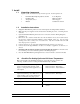
1. Install 1.1 Unpacking Components Unpack system, and check that components are present. Locate required tools. 1 1 1 1 1.2 Farm Hand Back UpTemperature Controller Installation Kit Temperature Sensor Manual Tools Required: Mini Screwdriver Wire Strippers Standard Screwdriver Installation Instructions 1. Hang Farm Hand Back Up with four screws and the plastic mounting brackets included. 2. Make sure all power supplies are disconnected before breaking any wires, or reaching into the enclosure.
2. Wire Stages Note: Refer to Wiring Diagrams in the back of this manual. 2.1 Illustration Of Farm Hand Back Up Stages The Farm Hand Back Up controls four stages. The Farm Hand Back Up can operate as a one room controller or as a two room controller. (See Section 3.2) ONE ROOM OPERATION Stage 1 Cooling Stage 2 Cooling Stage 3 Cooling Stage 4 Cooling (Optional) Power Cord One Room Operation The Farm Hand Back Up stages are shown. Stages 1, 2 and 3 are cooling stages only.
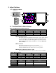
3. Adjust Switches 3.1 Switch Locations SWX1,2,3,4 1 ON 2 3 4 SWX1 OFF SWX5 SWX2 115v 230v 3.2 Farm Hand Back Up Switch Settings Table 1. Farm Hand Back Up DIP Switch Options Switch Position ON OFF 1 (Temp. Units) Fahrenheit (°F) Celsius (°C) Switch Numbers 2 3 (Operation) (Heat/Cool) Two Rooms See Table 2 One Room See Table 2 4 (Sensors) 2 Sensors 1 Sensor SWX1-Fahrenheit/Celsius This switch toggles between Fahrenheit and Celsius operation.
SWX4-One /Two Sensor Option For one room operation, this switch selects either one or two sensors. If the switch is in the ON position then the average temperature of Sensor 1 and Sensor 2 is used as reference and displayed as Room Temp. If the switch is in the OFF position then Sensor 1 is selected as the reference and displayed as the Room Temp.
One Room Operation For one room operation, stages 1, 2, and 3 are cool stages, and stage 4 is an optional heat or cool stage. (Optional settings are discussed later in this manual). The “Mode” button is used to select the Room Temp. indicator, the High Limit indicator, or the Low Limit indicator. Room Temp. displays the average temperature of the two sensors. The High Limit is set above the Target Temperature, and the Low Limit is set below a target temperature by using the + and - buttons.
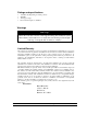
5.3 Normal Mode Parameters Room Temperature The average of the sensors located inside the house if one room operation is selected, or the temperatures of sensors 1 and 2 alternately displayed in the main display if two room operation is selected. High Limit The temperature inside the house at which the controller will turn on the first back up cooling stage. Low Limit The temperature inside the house at which the controller will turn on the first back up heating stage. 5.
Table 3. Program Mode Parameters Parameter Description P41 This is the software version number. Not Changeable. P42 This is the Setup Number which represents the controller type. Not Changeable. This is the calibration temperature for Sensor 1. Instructions: With the controller operating, use a digital thermometer or similar independent temperature measuring device to measure the temperature at Sensor 1 location.
Example Of Two Room Operation Set SWX2 (Section 3.2) for two room operation. Recall that for two room operation, the temperature reference of stages 1 and 2 is sensor 1, and the temperature reference of stages 3 and 4 is sensor 2. Sensor 1 is placed in room 1 and sensor 2 is placed in room 2. Stages 2 and 4 Set For Heat: In this example, the High Limit is set as 88ºF and the Low Limit is set as 68ºF. If stages 2 and 4 are set for heating (Section 3.
9. Wiring Diagrams Warning! Before connecting power to the machine, be sure to check the position of the voltage selector switch located next to the transformer on the relay board. Improper positioning of this switch will cause system failure. Warning! Do not connect more than twelve (12) amps of load to any one stage. All wiring connections for stages, inside the controller are made without terminals on the end of the wire.
9.1 Connecting Stages To Farm Hand Back Up (Single Pole) Inset 1 Inset 1 AC Power Cooling Stage 1 Stage 2 Stage 3 Stage 4 IN OUT IN OUT IN OUT IN OUT Temp.
9.2 Connecting Stages To Farm Hand Back Up (Double Pole) INSET 1 INSET 2 AC Power Cooling Stage 1 Stage 2 Stage 3 Stage 4 IN OUT IN OUT IN OUT IN OUT Sensor 2 Blk Wht Shld Wht Blk Heating INSET 1 INSET 2 Stage 2 Temp.
9.3 Sensor Wiring Temp. Sensors Sensor 1 Blk Sensor 2 Wht Shld Wht Blk Blk Wht Shld Sensor 2 Shld Wht Blk Sensor 1 Important! Shield Wire is not required. Care should be taken to insure that bare shield wires do not touch electronic components.
9.4 Wiring the Power Cord AC Power Hot Neu Gnd To Breaker Earth Ground Line 1 Line 2 Note: Make Sure that the SWX5 switch is set to the correct line voltage.
10. References Program Parameters P41- Software Version Number This parameter is a software version number. This is a read-only parameter. P42-Setup Number This parameter is the setup number. This is a read-only parameter. P51-Sensor 1 Temperature Calibration This is the calibration temperature for Sensor 1. Refer to Table 3 for setting instructions. P52-Sensor 2 Temperature Calibration This is the calibration temperature for Sensor 2. Refer to Table 3 for setting instructions.
11. Error Codes If your controller is displaying an “E1” or “E2”, etc. the controller has recorded an error. The controller records errors from sensor reading. Error Codes for the Farm Hand Back Up System Error Code Description E1 Sensor 1 Error Sensor 2 Error E2 E3 Sensor 1 and Sensor 2 Explanation Usually indicates a shorted sensor wire. Check sensor resistance. Usually indicates a shorted sensor wire. Check sensor resistance.
12. Temperature vs. Sensor Resistance Table The following chart gives the resistance when measured between the white and black sensor wires at a given temperature. To check a sensor, first know the temperature in the area, then, use a multi-meter to check the resistance. Resistance Kohms 32.654 32.158 31.671 31.191 30.72 30.257 29.802 29.355 28.915 28.482 28.057 27.777 27.363 26.957 26.557 26.164 25.777 25.523 25.147 24.777 24.413 24.055 23.82 23.472 23.13 22.793 22.572 22.244 21.922 21.71 21.397 21.
P 40-49 System Setup P41 = Software Version Number P42 = Controller Setup Number PS Sensor Calibration PS1 = Sensor 1 Calibration PS2 = Sensor 2 Calibration 4501-5083 4801-5048 Farm Hand Back Up 18