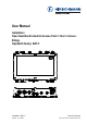
User Manual Installation Open Dual-Band Industrial Access-Point / Client / AccessBridge OpenBAT-Family: BAT-F Installation BAT-F Release 18 07/2020 Technical support https://hirschmann-support.belden.
The naming of copyrighted trademarks in this manual, even when not specially indicated, should not be taken to mean that these names may be considered as free in the sense of the trademark and tradename protection law and hence that they may be freely used by anyone. © 2020 Hirschmann Automation and Control GmbH Manuals and software are protected by copyright. All rights reserved.
Contents Safety instructions 7 About this manual 24 Key 25 1 Description 26 1.1 General description 26 1.2 Device name and product code 27 1.3 Device view 31 1.4 Power supply 1.4.1 Supply voltage with the characteristic value C (24 V DC ... 48 V DC) 1.4.2 Supply voltage with the characteristic value K (60 V DC ... 250 V DC / 110 V AC ... 230 V AC, 50 Hz ... 60 Hz) 1.4.3 Supply voltage with the characteristic value P (Power supply only through PoE) 1.4.
2 Installation 43 2.1 Checking the package contents 43 2.2 Installing and grounding the device 2.2.1 Installing the device onto or on a flat surface 2.2.2 Installing the device on a pole 2.2.3 Grounding the device 43 43 44 44 2.3 Installing an SFP transceiver (optional) 45 2.4 Installing the antennas 45 2.5 Connecting the power supply and the signal contact lines 2.5.1 Supply voltage with the characteristic value C (24 V DC ... 48 V DC) 2.5.
9 Disassembly 62 9.1 Removing the device 62 9.2 Removing an SFP transceiver (optional) 62 10 Technical data 63 10.1 General technical data 63 10.2 Dimension drawings 65 10.3 Radio technology 68 10.4 Roaming 68 10.5 Receiving sensitivity, transmit power, and data rate of the WLAN module version EWLAN1 (Approvals 2, characteristic value M or 9) 10.5.1 IEEE 802.11b 10.5.2 IEEE 802.11g 10.5.3 IEEE 802.11a 10.5.4 IEEE 802.11n 69 69 69 70 70 10.
12 Underlying technical standards 84 A Further support 86 6 Installation BAT-F Release 18 07/2020
Safety instructions WARNING UNCONTROLLED MACHINE ACTIONS To avoid uncontrolled machine actions caused by data loss, configure all the data transmission devices individually. Before you start any machine which is controlled via data transmission, be sure to complete the configuration of all data transmission devices. Failure to follow this instruction can result in death, serious injury, or equipment damage. General safety instructions You operate this device with electricity.
Indoor operator access area: The location is accessible without tools. The person responsible for the area has provided access for the operator intentionally. The operator knows of the access possibilities, regardless of whether they need a tool. If all the following requirements are fulfilled, you have the option of installing the device in the indoor operator access area. You supply 24 V DC to 48 V DC SELV voltage to the device. You install the device inside a building.
Qualified personnel have the following characteristics: Qualified personnel are properly trained. Training as well as practical knowledge and experience make up their qualifications. This is the prerequisite for grounding and labeling circuits, devices, and systems in accordance with current standards in safety technology. Qualified personnel are aware of the dangers that exist in their work.
Requirements for connecting electrical wires Before connecting the electrical wires, always verify that the requirements listed are complied with. The following requirements apply without restrictions: The electrical wires are voltage-free. The cables used are permitted for the temperature range of the application case. Relevant for North America: The power supply cables are suitable for ambient air temperatures of at least 167 °F (75 °C). The power supply cable wires are made of copper.
The following requirements apply without restrictions: Only for device The wire diameter of the power supply cable is at least 1 mm² (North variants featuring America: AWG16) on the supply voltage input. supply voltage with The following requirements are alternatively complied with: characteristic Alternative 1 The power supply complies with the requirements value C (24 V DC ... for a limited power source (LPS) as per EN 60950-1.
ATEX directive 2014/34/EU – specific regulations for safe operation In Ex zone 2, only devices with a corresponding label may be operated. When operating the BAT-F types with characteristic value G for Approvals 1 (ATEX zone 2), the following applies: Never use the supply voltage with characteristic value K (60 V DC ... 250 V DC / 110 V AC ... 230 V AC, 50 Hz ... 60 Hz) in Ex zone 2. II 3 G Ex nA IIC T4 Gc DEKRA 13ATEX0153 X −40 °F ... +158 °F (−40 °C ...
When operating the BAT-F types in explosion hazard areas Class I, Division 2, the following applies: Class I, Div. 2 Goups A, B, C and D Temperature code T4 List of standards Ambient: −40 °F ... +158 °F (−40 °C ... +70 °C; for characteristic value T and E for temperature range) Ambient: +32 °F ... +140 °F (0 °C ... +60 °C; for characteristic value S for temperature range) FM3600, FM3611 DO NOT OPEN THE DEVICE WHEN IT IS ELECTRICALLY CHARGED. Use this device only with the impact protection.
Ordinary Location, Non-Hazardous Area, Non-Explosive Atmosphere Class 1, Division 2 Groups A, B, C, D Hazardous Location or Zone 2 Explosive Atmosphere BAT-F WLAN-AccessPoint/-Client Relay contacts. Equipment with non-incendive field wiring parameters. Polarity is not relevant. THE RELAY TERMINALS ARE DEPENDENT UPON THE FOLLOWING ENTITY PARAMETERS: Vmax or 30 V U i l max or 90 mA Ii Ci Li 2 nF 1 μH Relais Supply voltage with characteristic value W: 16.
For Use in Hazardous Locations Class I, Division 2 Groups A, B, C, D: Only allowed for BAT-F model No’s. which are individually labelled “FOR USE IN HAZARDOUS LOCATIONS” Non-incendive field wiring circuits must be wired in accordance with the National Electrical Code (NEC), NFPA 70 , article 501. WARNING – EXPLOSION HAZARD – SUBSTITUTION OF ANY COMPONENTS MAY IMPAIR SUITABILITY FOR HAZARDOUS LOCATIONS OR EXPLOSIVE ATMOSPHERES.
E marking The labeled devices comply with the regulations contained in the following European directive(s): Regulation No. 10 of the Economic Commission for Europe of the United Nations (UN/ECE): Devices with an approval are labeled with the E type approval mark. The optical transceivers M-SFP-SX/LC-EEC and M-SFP-LX/LC-EEC can be used (relevant for devices with approval characteristic value M).
Notes for countries with the following country codes: AT BE BG CH CY CZ DE DK EE HR HU IE IT LI EL ES FI LT LU LV MT NL NO PL PT RO RS SE SI FR SK TR UK The RED compliance requires compliant operation of the device in the 5 GHz band channels. Compliant operation of the device is achieved by an unchangeable determination of the country setting. To obtain RED compliance, perform the work steps described in chapter “Obtain compliance for operation in the European Union” on page 54.
Notes for Germany (DE), Ireland (IE), and the United Kingdom (UK): DE IE UK Operation in the 5.8 GHz band at a radiated power (EIRP) >25 mW is subject to meeting the following conditions: Germany (DE) Frequency range: 5725 MHz to 5875 MHz Condition: The usage of this band is restricted to commercial public telecommunication services. Registration at the Federal Network Agency is required. Name and website of the competent authority: Bundesnetzagentur www.bundesnetzagentur.
FCC note Supplier's Declaration of Conformity 47 CFR § 2.1077 Compliance Information BAT-F U.S. Contact Information Belden – St. Louis 1 N. Brentwood Blvd. 15th Floor St. Louis, Missouri 63105, United States Phone: 314.854.8000 This device complies with part 15 of the FCC rules. Operation is subject to the following two conditions: This device may not cause harmful interference, and This device must accept any interference received, including interference that may cause undesired operation.
FCC ID: U99EWLAN1 IC: 4019A-EWLAN1 This equipment complies with FCC and IC RSS-102 radiation exposure limits set forth for an uncontrolled environment. Install and operate this equipment with a minimum distance of 19.7 in (50 cm) (related to a 9 dBi antenna) between the radiation source and your body. The antenna used for this transmitter must not be co-located with any other transmitters within a host device, except in accordance with FCC multi-transmitter product procedures.
Applies exclusively to device variants with approval for the 4.9 GHz band (Approvals 2, characteristic value P) according to FCC 47CFR Part 90 Subpart Y: Operation of the device in the 4.9 GHz band requires trained personnel familiar with the regulatory requirements for operation according to FCC 47CFR Part 90 Subpart Y. The 4.9 GHz band is a licensed band. State and local government entities that provide public safety services are eligible to apply for 4.9 GHz licenses.
To reduce potential radio interference to other users, the antenna type and its gain should be so chosen that the equivalent isotropically radiated power (EIRP) is not more than that permitted for successful communication.
BAT-ANT-N-5A-IP65 BAT-ANT-N-MiMo-9N-IP65 No No Yes Yes The use of antennas missing in this list is prohibited. The 5 GHz band is restricted to indoor usage.
About this manual The “Installation” user manual contains a device description, safety instructions, a description of the display, and the other information that you need to install the device. Documentation mentioned in the “User Manual Installation” that is not supplied with your device as a printout can be found as PDF files for downloading on the Internet at: https://www.doc.hirschmann.
Key The symbols used in this manual have the following meanings: Listing Work step Subheading Installation BAT-F Release 18 07/2020 25
1 1.1 Description General description The devices allow you to set up WLANs (Wireless Local Area Networks) in a local network. In contrast to a conventional network connection through copper cables and fiber optic cables, some of the communication is performed by means of a radio link. The devices allow you to install a new LAN or expand an existing LAN. Thanks to their high level of flexibility, the OpenBAT device is suitable for a wide range of applications.
The following installation options are available: Mounting on a flat surface Mounting on a pole You have the option of choosing various media to connect to the end devices and other network components: Twisted pair cable Multimode F/O Singlemode F/O There are convenient options for managing the device.
Item Characteristic 1 ... 5 6 ... 7 Devices of the OpenBAT family Country approvals 8 9 Example: Singapore Slot 1 Slot 2 10 11 Slot 3 Access point or client 12 Supply voltage 1 Characteri Description stic value BAT-F IP65/67 housing XX Example: SG W W 9 9 A C C K P W 13 Supply voltage 2 C K W 9 Table 3: 28 You can determine the current country approvals using the configurator (https:// catalog.belden.
Item Characteristic 14 Approvals 1 15 Approvals 2 16 Mounting 17 ... 18 Ethernet port 1 19 ... 20 Ethernet port 2 Table 3: Device name and product code Installation BAT-F Release 18 07/2020 Characteri Description stic value F Class I, Division 2 Groups A, B, C, D Hazardous Locations G ATEX Zone 2 I Substation applications (EN 61850) K Rail applications (EN 50155) M Motor vehicles applications (E typeapproval mark, ECE No.
Item Characteristic Characteri Description stic value E Extended with Conformal Coating -40 °F ... +158 °F (-40 °C ... +70 °C) K Extended with Conformal Coating and approvals 1, characteristic value K, railway applications: -40 °F ... +131 °F (-40 °C ... +55 °C) S Standard +32 °F ... +140 °F (0 °C ... +60 °C) T Extended -40 °F ... +158 °F (-40 °C ...
1.
4 5 6 7 8 9 10 11 12 32 Ethernet port 1 Combo port – you can use these ports for alternative purposes: 4a SFP slot for 1000 Mbit/s F/O connections Design: IP67-V1 connector according to IEC 61076-3-106, variant 1 4b alternatively, depending on Supply voltage with characteristic value C (24 V DC ... device variant 48 V DC) and K (60 V DC ... 250 V DC / 110 V AC ... 230 V AC, 50 Hz ...
1.4 Power supply Only for device variants featuring supply voltage with characteristic value C (24 V DC ... 48 V DC), K (60 V DC ... 250 V DC / 110 V AC ... 230 V AC, 50 Hz ... 60 Hz) or W (24 V DC): For redundant and failure-resistant power supply, you have the option of connecting multiple voltage sources in any combination at the same time. The device selects the used voltage source automatically. Switching to a redundant voltage source possibly occurs with a short delay.
1.4.4 Supply voltage with the characteristic value W (24 V DC) You have the following options to supply your device with voltage: Power supply through a 7/8" connector A 4-pin 7/8" plug is available for the power supply to the device. Further information: “Supply voltage with the characteristic value K (60 V DC ... 250 V DC / 110 V AC ... 230 V AC, 50 Hz ... 60 Hz)” on page 33 Power supply through PoE Your device is a PD (powered device).
100 Mbit/s half-duplex mode, 100 Mbit/s full duplex mode 1000 Mbit/s full duplex The socket housing is electrically connected with the device housing. 10/100/1000 Mbit/s twisted pair port Only device variants featuring supply voltage with characteristic value C (24 V DC ... 48 V DC) or K (60 V DC ... 250 V DC / 110 V AC ... 230 V AC, 50 Hz ... 60 Hz) have this port. The 10/100/1000 Mbit/s twisted pair port allows you to connect network components according to the IEEE 802.
M12 8-pin (“X”-coded) 7 8 1 6 2 3 5 36 4 Pin 1 2 3 4 5 6 7 8 10/100 Mbit/s RX+ RX− TX+ TX− — — — — 1000 Mbit/s BI_DB+ BI_DB− BI_DA+ BI_DA− BI_DC+ BI_DC− BI_DD− BI_DD+ PoE Negative VPSE Negative VPSE Positive VPSE Positive VPSE — — — — Installation BAT-F Release 18 07/2020
1.6 Connections for antennas The devices have 3 N sockets on each WLAN module. The "Antenna Guide" document provides an overview of the antennas that can be used as well as the suitable antenna accessories. The manual is available for download on the Internet: https:// www.doc.hirschmann.com 1.7 Display elements After the supply voltage is set up, the Software starts and initializes the device. Afterwards, the device performs a self-test. During this process, various LEDs light up.
Inverse flashing: the LED remains inactive for a very short time (about 10 × as long), then lights up for a much longer time (about 10 × as long). Flickering: the LED switches on and off at irregular intervals. Running light: coordinated glowing of several LEDs which gives the optical impression that a light source is moving from left to right and back. 1.7.2 Device state These LEDs provide information about conditions which affect the operation of the whole device.
ETH1, ETH2 (green/yellow LED) Meaning green yellow Ethernet connection active Data traffic glowing flickering 1.8 Management interfaces 1.8.1 V.24 interface (external management) This interface is designed as an 8-pin, “A”-coded M12 plug. The V.24 user interface is serial and allows you to connect the following devices directly: External management station (VT100 terminal or PC with appropriate terminal emulation).
Pins of the M12 socket Pin on the device 1 1 8 2 7 3 2 4 6 5 3 6 5 4 7 8 Table 4: Function Description of functions GND DTR TxD RxD DCD DSR RTS CTS Ground Data terminal ready Transmit data Receive data Data carrier detect Dataset ready Request to send Clear to send Pin assignment of the V.
Note: With the point-to-point WLAN line, the following pins are short-circuited at both ends: 2 (DTR) + 6 (DSR) 7 (RTS) + 8 (DSR) 1.8.2 USB interface This interface offers you the ability to connect the storage medium AutoConfiguration Adapter ACA21-M12 (EEC) / ACA22-M12 (EEC). This storage medium is used for saving/loading the configuration and diagnostic functions, and for loading the software. This interface is a 5-pin, “A”-coded M12 socket with shielding.
Note: The reset button is located behind a screwable IP65/67 pressureequalization element (Approvals 1 with characteristic value F and G), or a IP65/67 protection cap (Approvals 1 with characteristic value I, K, M and 9). The tightening torque is 4.42 lb-in to 8.85 lb-in (0.5 Nm to 1.0 Nm). You will find more information in the “User Manual Configuration Guide”, in the chapter “Using the Boot Configurations”. The manual is available for download on the Internet: https:// www.doc.hirschmann.
2 Installation The devices have been developed for practical application in a harsh industrial environment. On delivery, the device is ready for operation. To protect the exposed uninstalled contacts of the components from dirt, connect the individual system components in a dry and clean working area. The device fulfills the protection class IP65/67 under the following conditions, exclusively: All the connectors and cables connected also fulfill protection class IP65/ 67.
Requirements for the fastening components: The diameter of the mounting hardware is maximum 0.20 in (5 mm). The head diameter is maximum 0.47 in (12 mm). The diameter of a flat washer used is maximum 0.48 in (12 mm). Prepare the assembly at the installation site. See “Dimension drawings” on page 65. Install the device with suitable fastening components. Seal all unused connections and ports with protection screws. See “Accessories” on page 82. 2.2.
2.3 Installing an SFP transceiver (optional) Use only Hirschmann SFP transceivers which are suitable for usage with the device. See “Accessories” on page 82. The SFP mounting tool available as an accessory makes it easier for you to insert the SFP transceivers. See “Removing an SFP transceiver (optional)” on page 62. Remove the protection cap from the SFP transceiver. Push the SFP transceiver with the lock closed into the slot. 2.
If you would like to connect several antennas to a WLAN module, align the antennas so that the points of the antennas point away form each other in a star shape. Install at least one antenna on the WLAN module that you would like to use. Insert the terminating resistors available as accessories into the sockets not being used in order to avoid radio signals from one WLAN module being received by the other WLAN module.
2.5.1 Supply voltage with the characteristic value C (24 V DC ... 48 V DC) Perform the following steps for the supply voltage to be connected, or for device variants with 2 supply voltage connections of this type, for every supply voltage to be connected. Type and specification of the supply Pin assignment on the device voltage Rated voltage range DC: Minus terminal of the supply PP+ P24 V DC ... 48 V DC voltage Voltage range DC incl. maximum N.C. — tolerances: N.C. N.C. — N.C. 18 V DC ...
Type of the voltages that can be connected DC voltage Specification of the supply Pin assignment on the device voltage Rated voltage range DC: 60 V DC ... 250 V DC Voltage range DC incl. maximum tolerances: 48 V DC ... 320 V DC P+ PE AC voltage Rated voltage range AC: 110 V AC ... 230 V AC, 50 Hz ... 60 Hz Voltage range AC incl. maximum tolerances: 88 V AC ... 265 V AC, 47 Hz ...
2.5.4 Signal contact 1 4 2 3 Pin 1 2 3 4 Function Signal contact 2 Signal contact 2 Signal contact 1 Signal contact 1 Table 12: Pin assignment of the signal contact, 4-pin, “A”-coded M12 plug Only device variants featuring supply voltage with characteristic value C (24 V DC ... 48 V DC), K (60 V DC ... 250 V DC / 110 V AC ... 230 V AC, 50 Hz ... 60 Hz) or W (24 V DC) have a signal contact.
2.6.1 Connecting the power supply through a 7/8" connector You find the prescribed tightening torque of the locking screw in General technical data section on page 63. Plug the socket into the 7/8" connector on the device. Enable the supply voltage. 2.6.2 Connecting the power supply through PoE NOTICE MATERIAL DAMAGE In a PoE installation, use only devices that comply with the IEEE 802.3af/at standard. Failure to follow this instruction can lead to equipment damage.
2.7.2 10/100/1000 Mbit/s twisted-pair connection (optional) Further information: “10/100/1000 Mbit/s twisted-pair connection (optional)” on page 35 Connect the data cables according to your requirements. The tightening torque of the locking screw is 5.3 lb-in (0.6 Nm).
3 Making basic settings The IP parameters must be entered when the device is installed for the first time. The device provides the following options for configuring IP addresses: Input via the V.24 interface Entry via the HiDiscovery protocol in the applications HiDiscovery or Industrial HiVision Configuration via BOOTP Configuration via DHCP (Option 82) AutoConfiguration Adapter You will find more information in the “User Manual Configuration Guide”.
4 First login (Password change) Applies to devices with the following software release and later: HiLCOS 10.12-RU2 To help prevent undesired access to the device, it is imperative that you change the default password during initial setup. Perform the following steps: Open the Graphical User Interface, the Command Line Interface or LANconfig the first time you log on to the device. Log on to the device with the default password “private”. The device prompts you to type in a new password.
5 Obtain compliance for operation in the European Union For operation in the European Union, the device must comply with the Radio Equipment Directive (RED) 2014/53/EU. The RED compliance requires compliant operation of the device in the 5 GHz band channels. Compliant operation of the device is achieved by an unchangeable determination of the country setting. Make the country setting unchangeable using the Command Line Interface (CLI), the graphical user interface or the LANconfig software.
Note: To check the country setting and correct it, type no. Then check the country setting with the following command: ls Setup/WLAN/ Country. To obtain RED compliance, type yes. This makes the country setting unchangeable. Subsequently, the device restarts. Graphical user interface Open the Configuration > Wireless LAN > General dialog and select the desired country setting. Note: The country setting “Europe” is valid for all European countries.
To confirm your choice, click the “OK” button. In the LANconfig device overview, highlight the row containing the desired device. In the menu bar, select Device > RED compliance. Note: To check the country setting and correct it, click the “No” button. Then open the Configuration > Wireless LAN > General dialog. To obtain RED compliance, click the “Yes” button. This makes the country setting unchangeable. Subsequently, the device restarts.
6 Configuring the transmit power Note: This chapter does NOT apply to device variants with approval for the 4.9 GHz band (Approvals 2, characteristic value P). For device variants with approval for the 4.9 GHz band see “Configuring the transmit power for the 4.9 GHz band” on page 59. Note: The operator of a WLAN radio installation must adhere to the applicable transmission threshold values. Use the graphical user interface or the LANconfig software.
Subtract the cable and installed overvoltage protector attenuation from the antenna gain. Enter the calculated value in the “Antenna gain” field. To save the value, click the “Send” button.
7 Configuring the transmit power for the 4.9 GHz band Note: This chapter exclusively applies to device variants with approval for the 4.9 GHz band (Approvals 2, characteristic value P). Note: The operator of a WLAN radio installation must adhere to the applicable transmission threshold values. Use the graphical user interface or the LANconfig software. You can download the LANconfig software from the Hirschmann product pages (www.hirschmann.com).
To save the value, click the “Send” button.
8 Maintenance and service When designing this device, Hirschmann largely avoided using high-wear parts. The parts subject to wear and tear are dimensioned to last longer than the lifetime of the product when it is operated normally. Operate this device according to the specifications. Relays are subject to natural wear. This wear depends on the frequency of the switching operations.
9 Disassembly 9.1 Removing the device Disconnect the data cables. Disable the supply voltage. Disconnect the power supply cables and signal lines. Remove the antennas. Disconnect the grounding. 9.2 Removing an SFP transceiver (optional) To disassemble SFP transceivers, you require the SFP mounting tool available as an accessory . See “Accessories” on page 82.
10 Technical data 10.1 General technical data Weight Supply voltage with the characteristic value C Device variants featuring supply voltage with approx. 98.56 oz characteristic value P (Power supply only through (2800 g) PoE) Device variants featuring supply voltage with approx. 114.64 oz characteristic value C (24 V DC ... 48 V DC) or K (3250 g) (60 V DC ... 250 V DC / 110 V AC ... 230 V AC, 50 Hz ... 60 Hz) Device variants featuring supply voltage with approx. 105.
Supply voltage with the characteristic value K Supply voltage with the characteristic value P Supply voltage with the characteristic value W Power supply solely through a 7/8" connector Rated voltage range AC: 110 V AC ... 230 V AC, 50 Hz ... 60 Hz Voltage range including 88 V AC ... 265 V AC, 47 Hz ... 63 Hz maximum tolerances Rated voltage range 60 V DC ... 250 V DC Voltage range incl. maximum 48 V DC ... 320 V DC tolerances Connection type 3-pin, 7/8" connector Tightening 22 lb-in (2.
Climatic Minimum clearance around the conditions during device storage Ambient air temperaturea Humidity Air pressure Signal contact “FAULT” Switching current Switching voltage Pollution degree Protection Laser protection classes Degree of protection Top and bottom device side: 3.94 in (10 cm) Left and right device side: 0.79 in (2 cm) -40 °F ... +185 °F (-40 °C ... +85 °C) 10 % ... 95 % min. 700 hPa (+9842 ft; +3000 m) max. 1060 hPa (-1312 ft; -400 m) max.
74,37 2.93 311 12.24 322,46 12.70 mm inch Figure 3: Dimensions of the device variants with impact protection.
184 7.24 207 8.15 38,69 1.52 mm inch Figure 4: Distances of the suspension with impact protection.
10.3 Radio technology Antenna connection Range Encryption For each WLAN module: 3 × N socket Depending on the antenna used, frequency range and data rate IEEE 802.11i/WPA2 with passphrase or IEEE 802.1x and hardware-accelerated AES Closed Network WEP 64a WEP 128b WEP 152c User authentication 802.1x/EAP LEPS WPA1/TKIPd For more information, see the HiLCOS data sheet. Frequency range Support of 2.
10.5 Receiving sensitivity, transmit power, and data rate of the WLAN module version EWLAN1 (Approvals 2, characteristic value M or 9) The values shown in the following tables are the maximum values of the WLAN module version EWLAN1. The values are in no case to be perceived as a guaranteed property of the overall product. For some country profiles, the module reduces data rate and transmit power automatically. The reason for this are national standards. 10.5.1 IEEE 802.11b IEEE 802.
10.5.3 IEEE 802.11a IEEE 802.11a Frequency range 5.180 GHz to 5.825 GHz (for FCC: 5.180 GHz to 5.240 GHz and 5.745 GHz to 5.825 GHz) Data rate Typical transmit powera Typical receiving sensitivity 6 Mbit/s 16 dBm -93 dBm 9 Mbit/s 16 dBm -93 dBm 12 Mbit/s 16 dBm -93 dBm 18 Mbit/s 16 dBm -91 dBm 24 Mbit/s 16 dBm -88 dBm 36 Mbit/s 15 dBm -84 dBm 48 Mbit/s 13 dBm -80 dBm 54 Mbit/s 12 dBm -79 dBm Table 15: IEEE 802.11a, Frequency range 5.180 GHz to 5.825 GHz (for FCC: 5.180 GHz to 5.
IEEE 802.11n Frequency range 2.412 GHz to 2.472 GHz (for FCC: 2.412 GHz to 2.462 GHz) Coding Typical transmit power Typical receiving sensitivity MCS 14 15 dBm -73 dBm MCS 15 15 dBm -72 dBm MCS 16 23 dBm -87 dBm MCS 17 23 dBm -90 dBm MCS 18 23 dBm -86 dBm MCS 19 23 dBm -82 dBm MCS 20 16 dBm -79 dBm MCS 21 17 dBm -75 dBm MCS 22 17 dBm -73 dBm MCS 23 16 dBm -72 dBm Table 16: IEEE 802.11n, Frequency range 2.412 GHz to 2.472 GHz (for FCC: 2.412 GHz to 2.462 GHz) IEEE 802.
IEEE 802.11n Frequency range 5.180 GHz to 5.825 GHz (for FCC: 5.180 GHz to 5.240 GHz and 5.745 GHz to 5.825 GHz) Coding Typical transmit powera Typical receiving sensitivity MCS 15 14 dBm -73 dBm MCS 16 21 dBm -92 dBm MCS 17 21 dBm -91 dBm MCS 18 21 dBm -89 dBm MCS 19 21 dBm -84 dBm MCS 20 16 dBm -81 dBm MCS 21 15 dBm -77 dBm MCS 22 14 dBm -75 dBm MCS 23 14 dBm -73 dBm Table 17: IEEE 802.11n, Frequency range 5.180 GHz to 5.825 GHz (for FCC: 5.180 GHz to 5.240 GHz and 5.745 GHz to 5.
10.6 Receiving sensitivity, transmit power, and data rate of the WLAN module version EWLAN1 for device variants with approval for the 4.9 GHz band (Approvals 2, characteristic value P) Applies exclusively to WLAN module version EWLAN1 for device variants with approval for the 4.9 GHz band (Approvals 2, characteristic value P) according to FCC 47CFR Part 90 Subpart Y.
IEEE 802.11a Frequency range 4.940 GHz to 4.990 GHz Bandwidth 10 MHz Data rate Typical transmit power 9 Mbit/s 14 dBm 12 Mbit/s 14 dBm 18 Mbit/s 13 dBm 24 Mbit/s 12 dBm 27 Mbit/s 11 dBm Table 19: IEEE 802.11a, Frequency range 4.940 GHz to 4.990 GHz, Bandwidth 10 MHz, Channels 19-27 10.6.3 IEEE 802.11a, Bandwidth 20 MHz IEEE 802.11a Frequency range 4.940 GHz to 4.
10.7 Receiving sensitivity, transmit power, and data rate of the WLAN module version EWLAN2 for high-gain antennas (Approvals 2, characteristic value H) The values shown in the following tables are the maximum values of the WLAN module version EWLAN2 for high-gain antennas. The values are in no case to be perceived as a guaranteed property of the overall product. For some country profiles, the module reduces data rate and transmit power automatically. The reason for this are national standards. 10.7.
10.7.3 IEEE 802.11a IEEE 802.11a Frequency range 5.180 GHz to 5.825 GHz (for FCC: 5.180 GHz to 5.240 GHz and 5.745 GHz to 5.825 GHz) Data rate Typical transmit power Typical receiving sensitivity 6 Mbit/s 10 dBm -93 dBm 9 Mbit/s 10 dBm -93 dBm 12 Mbit/s 10 dBm -93 dBm 18 Mbit/s 10 dBm -91 dBm 24 Mbit/s 10 dBm -88 dBm 36 Mbit/s 9 dBm -84 dBm 48 Mbit/s 7 dBm -80 dBm 54 Mbit/s 6 dBm -79 dBm Table 23: IEEE 802.11a, Frequency range 5.180 GHz to 5.825 GHz (for FCC: 5.180 GHz to 5.
IEEE 802.11n Frequency range 2.412 GHz to 2.472 GHz (for FCC: 2.412 GHz to 2.462 GHz) Coding Typical transmit power Typical receiving sensitivity MCS 15 15 dBm -72 dBm MCS 16 23 dBm -87 dBm MCS 17 23 dBm -90 dBm MCS 18 23 dBm -86 dBm MCS 19 23 dBm -82 dBm MCS 20 16 dBm -79 dBm MCS 21 17 dBm -75 dBm MCS 22 17 dBm -73 dBm MCS 23 16 dBm -72 dBm Table 24: IEEE 802.11n, Frequency range 2.412 GHz to 2.472 GHz (for FCC: 2.412 GHz to 2.462 GHz) IEEE 802.11n Frequency range 5.180 GHz to 5.
IEEE 802.11n Frequency range 5.180 GHz to 5.825 GHz (for FCC: 5.180 GHz to 5.240 GHz and 5.745 GHz to 5.825 GHz) Coding Typical transmit power Typical receiving sensitivity MCS 16 8 dBm -92 dBm MCS 17 8 dBm -91 dBm MCS 18 8 dBm -89 dBm MCS 19 8 dBm -84 dBm MCS 20 3 dBm -81 dBm MCS 21 2 dBm -77 dBm MCS 22 1 dBm -75 dBm MCS 23 1 dBm -73 dBm Table 25: IEEE 802.11n, Frequency range 5.180 GHz to 5.825 GHz (for FCC: 5.180 GHz to 5.240 GHz and 5.745 GHz to 5.825 GHz) 10.
EMC interference emission EN 55032 FCC 47 CFR Part 15 Immunity Vibration Shock 10.9 Class B Class A IEC 60068-2-6 Test FC test level according to IEC 61131-2 IEC 60068-2-27 Test Ea test level in accordance with IEC 61131-2, EN 50155 Network range Note: The line lengths specified for the transceivers apply for the respective fiber data (fiber attenuation and Bandwidth Length Product (BLP)/ Dispersion). Product code M-SFP-... Wave length Fiber System Example attenuation for F/O cable lengtha -SX/LC...
Product code M-SFP-... Wave length Fiber -LH+/LC LH 1550 nm 9/125 µm -LH+/LC LH 1550 nm 9/125 µm System Example attenuation for F/O cable lengtha 15 dB ... 44.12 mi ... 30 dB 67.11 mi (71 km ... 108 km) 15 dB ... 44.12 mi ... 30 dB 79.54 mi (71 km ... 128 km) Fiber attenuation BLPb/ Dispersion 0.25 dB/km 19 ps/(nm×km) 0.21 dB/km (typically) 19 ps/(nm×km) Table 26: F/O port 1000BASE-FX (SFP fiber optic Gigabit Ethernet Transceiver) a.
11 Scope of delivery, order numbers and accessories Scope of delivery Number 1× 1× 1× 1× 3 × per WLAN module 2× 1 × or 2 × (depending on the device variant) 2× premounted 3× premounted 2× premounted 1 × per WLAN module premounted 1× premounted 1× premounted 3 × or 4 × premounted (depending on the device variant) Article Device Safety and general information sheet EU Declaration of Conformity Terminal cable: M12 plug, 8-pin on DB9 socket 3-dBi dipole dual-band antennas for initial operation Power supply
Number 1× 1× 1× 1× Article Device Safety and general information sheet EU Declaration of Conformity Power supply plug, for cable diameters of 0.24 in to 0.
Gigabit Ethernet SFP transceiver M-SFP-LX/LC M-SFP-LX/LC-EEC M-SFP-LH/LC M-SFP-LH/LC-EEC M-SFP-LH+/LC Order number 943 015-001 943 897-001 943 042-001 943 898-001 943 049-001 Other accessories 0986 EMC 600, field-attachable M12 plug for Gigabit Ethernet data cables 0986 EMC 102, field-attachable M12 plug for Fast Ethernet data cables Order number Available at ICOS 934 637-032 Available at Lumberg Automation 71327 50 Ω terminating resistors for sealing unused antenna connections, N 942 118-001 (10 pieces)
12 Underlying technical standards Name ATEX (2014/34/EU) CSA 22.2 No. 60950-1 ECE No. 10 EN 300 328 EN 301 489-1 EN 301 489-17 EN 302 502 EN 301 893 EN 45545-1 EN 45545-2 EN 50155 EN 55032 EN 60529 EN 60950-1 EN 60950-22 EN 61000-6-2 EN 61131-2 FCC 47 CFR Part 15 FM3600 FM3611 IEEE 802.1D IEEE 802.1Q IEEE 802.1w IEEE 802.11a/b/g/h/n IEEE 802.3 IEEE 802.3af UL 60950-1 84 ATEX – Intended use of equipment and protection systems in potentially explosive areas.
Name IEC/EN 61850-3 Communication networks and systems for power utility automation - Part 3: General requirements. The device has an approval based on a specific standard exclusively if the approval indicator appears on the device casing. The device generally fulfills the technical standards named in their current versions.
A Further support Technical questions For technical questions, please contact any Hirschmann dealer in your area or Hirschmann directly. You find the addresses of our partners on the Internet at http:// www.hirschmann.com. A list of local telephone numbers and email addresses for technical support directly from Hirschmann is available at https:// hirschmann-support.belden.com. This site also includes a free of charge knowledge base and a software download section.
Installation BAT-F Release 18 07/2020 87
Installation BAT-F Release 18 07/2020
Installation BAT-F Release 18 07/2020 89