KFR-3208GW/AE SPLIT TYPE AIR CONDITIONER INSTRUCTION MANUAL INSTALLATION Hisense Corporation
This air conditioner provides with cooling, heating, and drying functions. Details of the functions are below; refer to these descriptions when using the air conditioner. Compact Size This model is smaller than its predecessors and yet offers the same capabilities. Microprocessor Controlled Operation The interior compartment of the remote control unit contains several features to facilitate automatic operation, clearly displayed for easy use.
Contents Pardon not to inform you if the contents of the manual changes. Page Alert symbol 1 Caution statements 2 Composition of the air conditioner 3 Operation guide 8 Care and cleaning 15 Tips for energy saving 17 Troubleshooting 17 Schematic diagram 18 Appendix: Installation 19 Alert Symbols WARNING The symbol refers to a hazard or an unsafe practice which can result in severe personal injury or death.
Caution Statements WARNING 1.We recommend that this air conditioner be installed properly by qualified installation technicians in accordance with the installation instructions provided with the unit. 2.Before installation, check if the voltage of the electric supply in your home or office is the same as the voltage shown on the nameplate. WARNING 3.Do not install the air conditioner where there are fumes or flammable gases, or in an extremely humid space such as a greenhouse. 4.
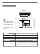
Composition of the Air Conditioner 1.Diagram of Structure Air intake grille INDOOR UNIT Air outlet Drain hose Refrigerant tubes Remote control unit OUTDOOR UNIT Air outlet The appearance of the appliance may differ from some pictures. NOTE This air conditioner consists of an indoor unit and an outdoor unit. You can control the air conditioner with the remote control unit.
2.Introduction of the Indoor ControI Unit INDOOR UNIT OPERATING lamp TIMER lamp POWER lamp IMPORTANT: POWER Avoid using radio equipment such as mobile phone near (within 1m) the indoor unit. Some radio equipment may cause maIfunction of the unit. HI POWER TIMER HIGH POWER lamp OPERATING ON/OFF If the troubIe happens, disconnect power and restart the air conditioner after a few minutes.
3.
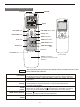
4.Introduction of the Remote control Unit SENSOR Transmitter A T E M P SS E T C 1HOUR 1С ʱ HOUR A Display ON OFF 1 HR A FAN SPEED TEMP FAN SPEED selector button 1 HR. TIMER button H . .P O HIGH POWER button N /O FF ON/OFF button TEMP.
Remote Control Unit(continued) TIMER ON button TIMER OFF button TIMER SET/CANCEL button MODE selector button (AUTO) (HEATING) (DRY) (COOLING) (FAN) FLAP button FAN SPEED selector button 1 HR TIMER button (1-HOUR OFF TIMER) ! :The air conditioner starts at the set time. :The air conditioner stops at the set time. This button is used to set/cancel the time at which you wish the air conditioner to go on or off. Use this button to select AUTO, HEATING, DRY or COOLING mode.
Operation Guide HOW TO INSTALL BATTERIES 1. Slide the cover in the direction indicated by the arrow and remove it. 2. Install two AAA alkaline batteries. Make sure the batteries point in the direction m arked in the battery compartment. 3. Use a thin object such as the tip of a pen to press the ACL button. + - + ! NOTE Sliding cover Replace the batteries when the remote control unit's display fails to light, or when the remote control unit cannot be used to change the air conditioner's settings.
Operation with the Remote Control Unit(continued) C A A 1 HR FAN SPEED TEMP STEP 4 H . .P O FLAP N /O FF STEP 2 MODE STEP 1 STEP 5 ON SLEEP SET OFF CANCEL ACL A/C SENSOR NOTE STEP 3 Check that the circuit breaker on the power panel is turned on and that the operation selector of the indoor unit is in the ON position. If the automatic operation settings of the unit do not meet your needs, press the setting buttons as described below and change the settings as desired.
Adjusting the Fan Speed A. Automatic A Simply set the FAN SPEED selector to the position. A microprocessor in the air conditioner automatically controls the fan speed when the A mode is selected. When the air co nditioner starts operating, the difference between the room temperature and the set temperature is detected by the microprocessor which then automatically switches the fan speed to the most suitable level. B.
Night Setback / Simultaneous Use Energy Saving TEMP SET C A A 1 HR FAN SPEED TEMP H . .P O FLAP N /O ¡ñ Night Setback Mode Night Setback Mode is used for saving energy. Press the SLEEP button in operation. The mark appears in the display. To release the night setback function, press the SLEEPbutton again. FF NOTE This function loses in automation or airflow mode.
Using the 12-Hour ON and OFF Timer 1.TIMER ON mode (Example) After the length of time set for TIMER ON elapses, the unit begins operating. The display depicted at left indicates that the air conditioner will begin operating in three hours. Setting Procedures: C STEP 1 Press the MODE button and set the desired operation mode and press the ON/OFF operation button. STEP 2 Press the timer ON button to set the time at which you want operation to begin.
Using the 1-Hour OFF Timer This function causes the unit to operate for one hour and then stop, regardless of whether the unit is on or off when this button is pressed. The 1HOUR indicator in the display indicates that this function is operating. C 1HOUR 1С ʱ Setting procedure: A Regardless of whether the unit is operating or stopped, press the 1 HR .TIMER button. A 1HOUR 1 HR Appears in the display. FAN SPEED TEMP H . .
Special Remarks Heating ( ) Operation Heating performance Because this air conditioner heats a room by drawing on the heat of the outside air (heat pump system), the heating efficiency will fall off when the outdoor temperature is very low. If sufficient heat cannot be obtained with this air conditioner, use another heating appliance in conjunction with it. Defrosting When the outdoor temperature is low, frost or ice may from in the heat exchanger coil, reducing heating performance.
Operation without the Remote Control Unit POWER HI POWER TIMER OPERATING ON/OFF button ON/OFF If you have lost the remote control unit or it has trouble, follow the steps below. 1.When the air conditioner is not running If you want to turn on the air conditioner, pressing the ON/OFF button once. 2.When the air conditioner is running If you want to turn off the air conditioner, pressing the ON/OFF button once.
Care and Cleaning (continued) Anti-Mold Filter How to remove the anti-mold filter The anti-mode filter behind the air intake grille should be checked and cleaned at least once every three weeks. 1.Grasp both ends of the air intake grille and pull it out and up. 2.Push the anti-mold filter up slightly, and then pull it down. Air intake grille Anti-mold filter Anti-Mold Filter Cleaning How to replace the anti-mold filter Use a vacuum cleaner to remove light dust.
Tips for Energy Saving Do not Do Block the air intake and outlet of the unit. If they are obstructed, the unit will not work well, and may be damaged. Let sunlight directly into the room. Use sunshades, blinds or curtains. If the walls and ceiling of the room are warmed by the sun, it will take longer time to cool the room. Always try to keep the air filter clean. (Refer to Care and Cleaning .)A clogged filter will impair the performance of the unit.
Schematic Diagram 1. Refrigerant Flow Diagram Outdoor unit Indoor unit Compressor Wide tube Accumulator Wide service valve Heat exchanger Heat exchanger 4-way valve Capillary Narrow tube Narrow service tube Capillary Cooling cycle Heating cycle Check valve 2. Permitted ambient temperature for the air conditioner is following:-7 ~+43 . 3.
Appendix: Installation Make a wood or metal frame to support the appliance if necessary. ----When the appliance is mounted in a room, Properly insulate the tube of indoor unit, and make sure there is no water drops on the appliance or on the floor. ----When the appliance is installed on a damp or uneven area, Make a flat concrete base and place the base under the outdoor unit. ----When the appliance is installed in an area of strong winds.
Appendix: Installation 2. Location 2-1 Indoor unit 2-2 Outdoor unit The outdoor unit should be installed away from the following: Heat source and fan exhausting ; Director sunlight; WARNING: Maintain the required space around the appliance to prevent overheat.
Appendix: Installation 3. Installation of the indoor unit Wall plate Fixing screw Remove the wall plate (1)Remove the fixing screws and keep them for future use (not used during installation). (2)Press the two triangular signs on the outer shell and remove the fixing clip. (3)Remove the wall plate. Fixing clip Mount the wall plate (1)Determine the correct position of the plate with a level (never use the naked eyes!). The plate should be level.
Appendix: Installation (3)Any part of the drainpipe should be below the outlet of the indoor unit and the joints should be wrapped with waterproof adhesive tape to prevent leakage of condensed water. (4)Bind the tubes, wires and the drainpipe tightly with binding tape, with the drainpipe under the wires. (5)Press down the clamping plate of the tubes and fix the bound wires.
Appendix: Installation 5.Air purging Air and moisture remaining in the refrigerant system have undesirable effects as indicated below. Therefore, they must be purged completely.
PACKING LIST NAME AMOUNT 1. OUTDOOR UNIT 1 2. POWER CABLE 1 3. DRAINAGE ELBOW * 1 4. AIR FRESH FILTER 1 5. INDOOR UNIT 1 6. MANUAL 1 7. REMOTE CONTROL UNIT 1 8. BATTERY 2 9. NAIL SPECIAL 6 NO. THE SYMBOL "*" STANDS FOR THE PART TO BE PICKED AND MADE PURCHASE.