LCD Television Service Manual Chassis: MTK8222 Product Type:LCD42P69P、LCD47P69P Ver 1.0 Hisense Electric Co.,Ltd.
LCD TV Service Manual Contents Contents.......................................................................................................................................................................- 2 Service Manual ...........................................................................................................................................................- 3 1. Precautions and notices.....................................................................................................
LCD TV Service Manual Service Manual 1. Precautions and notices BEFORE SERVICING THE LCD TV, READ THE SAFETY PRECAUTIONS IN THIS MANUAL. WHEN REPLACEMENT PARTS ARE REQUIRED, BE SURE TO USE REPLACEMENT PARTS SPECIFIED BY THE MANUFACTURER. Proper service and repair is important to the safe, reliable operation of all Hisense Electric Co., Ltd Equipment. The service procedures recommended by Hisense and described in this Service Guide are effective methods of performing service operations.
LCD TV Service Manual which are not recommended by Hisense, must first satisfy himself thoroughly that neither his safety nor the safe of the equipment will be jeopardized by the service method selected. Hereafter throughout this manual, Hisense Electric Co., Ltd will be referred to as Hisense. 1.1 Warning 1.1.1 Critical components having special safety characteristics are identified with a by the Ref. No. in the parts list.
LCD TV Service Manual that you are connected with the same potential as the mass of the set by a wristband with resistance. Keep components and tools also at this same potential. 1. Never replace modules or other components while the unit is switched on. 2. When making settings, use plastic rather than metal tools. This will prevent any short circuits and the danger of a circuit becoming unstable. 1.1.
LCD TV Service Manual touch EMI ground part and Heat Sink of Film Filter. (2) Do not supply a voltage higher than that specified to this product. This may damage the product and may cause a fire. (3) Do not use this product in locations where the humidity is extremely high, where it may be splashed with water, or where flammable materials surround it. Do not install or use the product in a location that does no satisfy the specified environmental conditions. This may damage the product and may cause a fire.
LCD TV Service Manual otherwise, this can lead to fire or electric shock. (10) If the power connector or the connector of the power cable becomes dirty or dusty, wipe it with a dry cloth. Otherwise, this can lead to fire. (11) Use only with the cart, stand, tripod, bracket, or table specified by the manufacturer, or sold with the apparatus. When a cart is used, use caution when moving the cart/apparatus combination to avoid injury from tip-over. 1.
LCD TV Service Manual equipment and the high voltage power supply block, it can result in electric shock or activation of the leakage-detection circuit breaker. • When installing the LCD module in, and removing it from the packing carton, be sure to have at least two persons perform the work.
LCD TV Service Manual that they are not damaged and their materials do not deteriorate over long periods of time. Therefore, route the cables and fix the cables to the original position and states using the wire clamps. • Perform a safety check when servicing is completed. Verify that the peripherals of the serviced points have not undergone any deterioration during servicing.
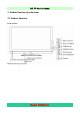
LCD TV Service Manual 2. Product Function Specifications 2.
LCD TV Service Manual Back Cabinet Hisense Confidential - 11 -
LCD TV Service Manual 2.
LCD TV Service Manual 3. LCD Panel Spec LCD42P69P Panel: LC420WUN-SBD1 \ROH SN:1056497 3.1General Description 3.
LCD TV Service Manual LCD47P69P Panel: LC470WUN-SBC1\ROH SN:1056802 3.
LCD TV Service Manual 3.
LCD TV Service Manual 4. Chassis Layout and Overall Wiring Diagrams Boards and Chassis Layout LCD42P69P: No Description Part No. Type/Model PCB/ Model (1) Main board 118963 RSAG2.908.1497\ROH RSAG7.820.1637\VER.D\ROH (2) Power board 116947 RSAG2.908.1192-7\ROH RSAG7.820.1185\VER.D\ROH (3) Keypad PCA 113354 RSAG2.908.1088\ROH RSAG7.820.1101\VER.B\ROH (4) IR board 113523 RSAG2.908.1029-2\ROH 40RSAG7.820.996\VER.C\ROH (5) Led board 117467 RSAG2.908.1279-1\ROH RSAG7.820.1343\VER.
LCD TV Service Manual 5. Factory/Service OSD Menu and Adjustment 5.1 To enter the Factory OSD Menu a. With factory RC (remote control) 1. Press “M” button and enter factory mode. 2. Press “Menu” button and enter factory OSD menu. 3. Press “CH+”/“CH-” button select the function menu, press “VOL+”/“VOL-” enter the selected function menu. Press “VOL+”/“VOL-” button adjust values in the menu. b. With user’s RC 1. Power TV On 2. Press Menu button and call up User OSD Menu 3. Select Audio-> Balance 4.
LCD TV Service Manual e、Close the OSD menu after 5 seconds. 5.2.2 Factory Option Item 0 White Balance Item 1 Note R DRV Red Driver adjust G DRV Green Driver adjust B DRV Blue Driver adjust R CUT Red Cut adjust G CUT Green Cut adjust B CUT Blue Cut adjust Note: Before adjusting, please change to desired source. Different source has different WB values.
LCD TV Service Manual Scart MODE “M” is only used for factory production. Version Info Version: Date: Note: Software version info of the TV, readable only. Clean Protected Yes or No Current Software version The date of current version Clean data except WB data and Auto Color data Clean all data Clean All Note: The factory menu date varies according to different sources. Incase changing the factory data by error, you can choose to “Clean Protected”, by which you can resume the default value.
LCD TV Service Manual Volume 25 Volume Mid Volume 75 Volume Max Audio Mode Audio Mode 120HZ 500HZ 1.
LCD TV Service Manual 6 Software Upgrading The first upgrading method: The software is upgraded by a burning toll-MtkTool, which can burn the program file *.bin to the main board of the unit. 6.1 Get ready for upgrading 6.1.1 Install the driver Double click the icon MTKtools2.44.04+cp210xDriver.rar , install the driver. Select the default value, the driver will be installed step by step. 6.1.2 Hardware connecting Connect the unit to your pc with a USB-to-serial port cable.
LCD TV Service Manual For the first connecting, the pc will recognize and automatically install the USB device. The process is just like the installation of a mini disk, see the following picture.
LCD TV Service Manual 6.2 Upgrading with the MtkTool MTKtool is a green program needing no installation. It is saved in the folder . There are five folders/files in this folder altergether. The MtkTool using log is restored in the MtkLog folder. It records the running time and date whenever the tool is used. The log will be a txt file named by the date and time. After connecting the TV with your PC, double click icon, open the MtkTool.
LCD TV Service Manual 2—Refer to the next page instruction to select the communicate port. 3—Press the icon beside the baud rate and make sure it is green as the below picture. 4—Set the flash baud rate to 115200 as the below picture. 5—Click the browse button to select the *.bin file that will be updated. 6—Click the “start” button to update software. Select mode Communicate of Flash chip port Set Flash Select *.
LCD TV Service Manual Open “Device Manager” and find which port is connected with the TV. In this operation, COM5 is connected to the TV; so, select “COM5” in the MtkTool main interface. Select the right baud rate according to chip model. For this unit( chip model is MT8226), select 115200..So choose “Auto Set Flash BaudRate” Note: Whether or not click the “Auto Set Flash Baud Rate” in the “window” menu depends on the chip type.
LCD TV Service Manual Click “Browse” button, find the upgrading program file, and select it. Press “Upgrade” button and start upgrading. The following interface appears on the screen, indicating upgrading successfully.
LCD TV Service Manual 6.3 Update with USB directly The second update method is with USB directly: MTK8222 Series can update with USB, the software name should be HISENSE.bin. The Updating Steps is set the Source to "DMP interface", insert the USB(the update file HISENSE.bin,which should be in root directory),The TV automatic identify the upgrading software. step by step according as the informations of the upgrading process.
LCD TV Service Manual After upgrading, you must confirm the software in the Factory Menu and you'd better "CLEAR UNPROTECTLY".
LCD TV Service Manual 7. Troubleshooting 7.
LCD TV Service Manual 7.
LCD TV Service Manual 7.
LCD TV Service Manual 7.
LCD TV Service Manual 7.
LCD TV Service Manual 7.
LCD TV Service Manual 7.
LCD TV Service Manual 8. Explode View 9.
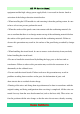
5 4 3 2 1 5V_M 5V_M 12V_M C817 10uF 0.1uF R668 CE64 CE69 4.7k SCT2_AUL_OUT 47 10K 12V_M 2,11,14 1 1 3904 C276 2.2uF R674 10k A_MUTE 0/NS AL2 R697 0 AOTL 10K 2 +3V3 10uF/16v Q53 1 47k R686 1 3904 3904 2 R695 R705 +3V3 2,3,4,6,7,11,14 10k C278 2.2uF R699 OFF_MUTE AL1 0 R675 R688 R687 47 8.2k 47 8.
5 4 MT8222_P1V1 (DDR1) 3 2 1 VERSION V1.
5 4 3 2 1 5V_M D188 MAIN POWER +5VS 5V_M 12V_M BL-ON/OFF BL-ADJUST 12V_M +5VS +5VS 1 2 3 4 5 6 7 8 9 10 11 12 13 5V_M SW R259 1K + CE66 470uF/16v +3V3 B240A D187 FB64 CB218 0.1uF +3V3 +3V3 3,4,6,7,11,13,14 12V_M + CE68 220uF/16v CB219 0.1uF 12V_M 12V_M 0603_Bead 11,14 +5V_ON B240A 2008.6.4 SW +5V_ON +5V_ON VPA D +5V_TUNER 12V_M UP31 HIGH :POWER OFF 12V_M +5VS 3 1 2 3 4 5 6 7 8 9 10 11 12 13 14 CN2 +5V_ON +5V_ON B240A D185 5V_M R258 Q29 3904 CE83 + CB217 0.
5 4 3 2 System I2C RDQ0 RDQ1 RDQ2 RDQ3 RDQ4 RDQ5 RDQ6 RDQ7 RDQS0 RDQM0 DV10 RDQM1 RDQS1 RDQ8 RDQ9 RDQ10 RDQ11 RDQ12 RDQ13 RDQ14 RDQ15 AV12_MEMPLL RCLK0# RCLK0 RCKE RA12 RA11 RA9 RA8 RA7 RA6 RA5 RA4 RWE# RCAS# RRAS# RCS# RBA0 RBA1 RA10 RA0 RA1 DV10 RA2 RA3 MEM_VREF C980 0.
5 4 3 2 1 DV10 ( Bypass CAPs arround MT8222 ) DV10 DV10 2,3 +3V3 2,3,6,7,11,13,14 DV33 3 AV12 2 DDRV 2,3,5 +3V3 +3V3 add by 08/03/20 DV10 DV33 DV33 AV33_SIFDIG + CE62 470uF/10v-LowESR CAP C886 4.7uF/10V C887 0.1uF C888 3300pF C889 0.1uF C890 6800pF C891 0.1uF C892 3300pF C893 0.1uF C894 0.
5 4 3 2 1 RDQS0 RDQS1 VTT 增加FB31 20080911 ( DDR1 DRAM With Termination ) RDQS0 3 RDQS1 3 RDQM0 RDQM1 RDQM0 3 RDQM1 3 RWE# RCAS# RRAS# RCS# FB31 0603/181 RCKE DDRV DDRV U1 MEM_DQ0 D MEM_DQ1 MEM_DQ2 MEM_DQ3 MEM_DQ4 MEM_DQ5 MEM_DQ6 MEM_DQ7 MEM_DQS0 MEM_DQM0 MEM_WE# MEM_CAS# MEM_RAS# MEM_CS# MEM_BA0 MEM_BA1 MEM_ADDR10 MEM_ADDR0 MEM_ADDR1 MEM_ADDR2 MEM_ADDR3 1 2 3 4 5 6 7 8 9 10 11 12 13 14 15 16 17 18 19 20 21 22 23 24 25 26 27 28 29 30 31 32 33 VDD DQ0 VDDQ DQ1 DQ2 VSSQ DQ3 DQ4 VDDQ DQ5 DQ6
5 4 System E2PROM 3 Wangxiyu 20080721 System Reset# +3V3 2 1st UART IF ( For Code download and Debug ) +3V3 Wangxiyu 20080721 1 PWM2 ORESET# +3V3 PWM2 3 ORESET# 3 OIRI 3 U0RX U0TX 3 3 U1RX U1TX 3 3 USB_DP0 USB_DM0 3 3 USB_DP1 USB_DM1 3 3 +3V3 10K R198 PWM2 R31 R36 R73 VCC NC WP NC SCL NC SDA GND R21 Q1 3904 D1 1N4148 R22 47K R60 R61 4.7K 4.
5 4 3 2 1 +3V3 +3V3 HDMI port 0 +5VS D153 CEC HDMI_PLUGPWR0 1 OPWR0_5V D P13 RX0_2 0 2 CB140 0.1uF BAT54C CB138 0.1uF R96 47K 1 2 3 4 5 6 7 8 9 10 11 12 13 14 15 16 17 18 19 RX0_2B RX0_1 RX0_1B RX0_0 HDMI_PLUGPWR0 3 ESD 1.
5 4 3 AV1+S-Video1 Input 2 NEAR CONNECTOR 1 NEAR IC P16B 左 FB1 8 GND 9 AV1_IN AV1_IN 下 R441 10 GND 11 红 SIGNAL 12 14 13 12K AV1L_IN R440 100 C1 47nF CVBS1 CVBS1 CVBS2 CVBS3 CVBS4 C5 47pF FB2 AV1_R 3 3 3 3 0 1 SY1_IN SY1 R3 100 C4 47nF D CVBS2 R443 10K D65 EZJZ0V800AA GND 1 D64 R442 10K P17 2 EZJZ0V800AA 2 Cin Yin GND GND GND AV2 Input 3 1 2 4 7 6 5 R4 75 D60 EZJZ0V800AA SC1_IN SY1_IN FB3 SC1 R5 100 C7 47nF 1 AV1_R GND 2 R7 75 D63 EZJZ0V800A
5 4 3 2 NEAR IC NEAR CONNECTOR C58 FB16 Y0_IN SCT1_R 1 R41 2 Y0_IN_GND R80 68 C62 NS/4.
5 4 3 2 1 Only for EU, US not stuff D D NEAR CONNECTOR Near swtich SCT1_AUR_OUT 2 SCT1_AUR_IN AUDIO_OUT_L 3 SCT1_AUL_OUT GND_Audio 4 GND_Blue 5 SCT1_GB_GND AUDIO_IN_L 6 SCT1_AUL_IN R39 100 C65 47nF CVBS5 SCT1_FS_IN GND_Green SCT1_GB_GND 2 SCT1_AVI_GND R53 PB0_IN D82 EZJZ0V800AA SCT1_R_GND 13 14 Red_I/O 15 SCT1_R_IN Fast_Blanking 16 SCT1_FB_IN SCT1_AVI_GND VIDEO_OUT(Composite) 19 SCT1_AV_OUT VIDEO_IN(Composite) 20 SCT1_AV_IN Common_GND 21 SCT1_AUR_OUT SCT1_A
5 4 3 2 1 TUNER_IF 12 13 14 15 16 17 18 19 U15 GND3 GND2 GND1 GND4 GND5 GND6 GND7 GND8 +5V_TUNER +5V_TUNER +5V_TUNER +5V_TUNER +5V_TUNER 2 IF_TUNER C613 CE94 + 10uF/16V R-CAPC2012N-HX D D81 NS/1N4148 R644 47K R642 R643 TU_33V CB203 0.1uF CB204 4.7uF R-CAPC1005L-HX R-CAPC2012N-HX C616 C617 22pF 22pF 33 33 SDA_V50 SCL_V50 R-SOT3N-0.95-2.75-HX TU_33V QF2 2N7002 N-MOSFET 2 3 OSDA0 GND +3V3 CE36 10uF/50V D9 0.1uF/50V C33V1 IN4148 Q32 CE39 1uF/50V C1815TL1 1 SDA_V50 R204 4.
5 4 3 2 AUD_LOUT CA154 10uF/10v RA110 20K AUD_L AUD_ROUT CA155 10uF/10v RA111 20K AUD_R 1 5V_M 5V_M AMUX_5V FBA1 D 5V_M 5V_M 2,3,6,8,13,14 D 0603_Bead CA69 4.7uF/16v CA68 0.1uF + CA71 100uF/16v CA70 0.1uF AMUX_5V 10K C415 C354 C381 C396 2.2uF 2.2uF 2.2uF 2.2uF 12 14 15 11 X0 X1 X2 X3 X Y0 Y1 Y2 Y3 VCC GND INH VEE Y MUX1-L 13 2.2uF 2.2uF 2.2uF 2.
5 4 3 2 1 Wangxiyu 20080721 +3V3 LVDSVDD +5V_ON 5V_M LVDS POWER 12V_M R352 4.7K/NS R-RESC1005L-HX VBR_OUT R428 L63 FB(1206) 1 2 3 4 C377 D C329 1uF S1 G1 S2 G2 R349 47k 10uF/NC D1 D1 D2 D2 P-CH LVDSVDD 8 7 6 5 R355 OSCL0R356 4.7K R-RESC1005L-HX AO4459 R-SOIC08N-1.270-6.00-HX 0R NS/0R VBR_OUT GND O0P O1P O2P OCKP O3P O4P GND E0P E1P E2P ECKP E3P E4P C378 0.