LogicPLUS 42S-C & LogicPLUS 128S-C Programming Manual rAINPRO ® Intelligent Irrigation Solutions TM Two-Wire Irrigation Controller Made in the USA May 15, 2014 P.O. Box 929 • 556 S. Mirage Avenue • Lindsay, CA. 93247 For Technical Assistance Call: 800-468-0071 ext. 115 Designed and Manufactured by RainPro® Lindsay, CA.
Table of Contents Features and Specifications.................................................................... 3-6 Installation Do’s and Don’ts........................................................................ 7 Installing the LogicPLUS-S......................................................................... 8 Programming the LogicPLUS-S............................................................ 9-26 Receiver Programming........................................................................
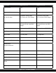
FEATURES LogicPLUS-S 42 LogicPLUS-S 128 Stations Available 1-42 1-128 Programs Available 8 16 Run Time Per Station 0-10 hours, 59 min. Max. 0-27 hours-use 250% budget 0-10 hours, 59 min. Max. 0-27 hours-use 250% budget Program 6 0-59 min., 59 sec. 0-2 hours 30 min.-use 250% budget 0-59 min., 59 sec. 0-2 hours 30 min.-use 250% budget Calendar 0-28 days Max., ODD/EVEN 0-28 days Max., ODD/EVEN Water Budget 0-250% 0-250% Rain OFF Days 0-31 days Max. 0-31 days Max.
Field Wire Outputs Minimum Wire Size Maximum Wire Run Maximum Number of Receivers Receivers Programmable and Re-Programmable On Board Receiver Programming Capability Remote Receiver Programming use LP-HHRP Security Password 4 14 gauge 12,000 Feet 80 Yes 4 14 gauge 12,000 Feet 128 Yes Yes Yes Yes Yes Yes Yes Enclosure: Box - Stainless steel, locking, wall or pedestal mount. Pedestal – Stainless steel See diagram page 45 for box and pedestal dimensions.
Wire type: Single strand direct burial, Jacketed two conductor, or Stranded. No “Special” wire required. Wire Size: Minimum 14 gauge. Wire Runs: Maximum 12,000 feet for each two wire path (4 available). Branching & Teeing: Allowed but should be well planned and minimized. Wire Color: Use of different colored wires is recommended for ease of wire run identification. Use different colors for each run and every tee or branch.
Pump Start Relay/Fertigation Relay When using a pump start relay, the relay shall be a 24 VAC coil with a maximum inrush of .35 amps and holding .25 amps. The relay will act as a slave to the magnetic relay to control the pump motor. You can use up to a 5hp Hit Products pump start relay attached directly to the relay terminal. See diagram on page 44 Rain Sensor The Rain Sensor terminal is located on the bottom right of the Controller board labeled “RAIN OFF.
LogicPLUS-S Installation “Do’s & Don’ts” For Warranty To Be Valid, Installation Must Comply To All Instructions Below 1. Use only LP-RP Receivers (Gray Molded Box) with the LogicPLUS-S Controllers (LP-42, LP- 128 and Uni-2 Plus). DO NOT use the L-RP (Black Molded Box) Receivers with the Logic PLUS-S Controllers. Do not use the LP-RP (Gray Box) Receiver with the Logic 1, Logic 2, Logic 3 or Uni-2 Controller. 2.
INSTALLING THE LogicPLUS-S Mounting the controller...........When selecting the controller installation location, make sure controller and all related wiring is a minimum of 15 feet from any high voltage control boxes, pumps or any high voltage equipment. This irrigation controller is a computer and should be installed accordingly. When mounting the LogicPLUS-S indoors, notice the “keyhole” shaped mounting slot as well as 2 mounting holes on the back of the controller.
PROGRAMMING THE LogicPLUS-S 42 and LogicPLUS-S 128 CONTROLLERS The LogicPLUS-S Controllers are so easy to program because the four sets of black up/down arrow buttons correspond to whatever is directly above them in the display. You can toggle between ON and OFF, set hours, minutes, and seconds, or even select program numbers, valve numbers, and start times simply by using these up/down buttons located directly under their functions.
PROGRAMMING CONTROLLER SET 1 SET 2 SET 3 SET 4 10 10 LogicPLUS-S Two-Wire Controller SET 5
Position 1 | | Current Date / Time || Position 1 SET 1 SET 2 SET 3 SET 4 SET 5 Current Time: Set time of day, use set 1 to change display from time to date, use set 2 to set hour (this will set A.M. or P.M.), use set 3 to set minutes, use set 4 to “Zero out” seconds. Current Date: Set today’s Date, use set 2 to set month, use set 3 to set day of month, use set 4 to set year, i.e.
Position 2 | | Valve Run Times | | Function Button-Pre Wet Function Button-Fertigation Position 2 Set Valve Run Times: Use set 1 to choose the program, use set 2 to choose the valve number, use set 3 to set hours, use set 4 to set minutes. Input the total irrigation run time desired for each valve, including pre wet and fertigation time. Pre Wet and Fertigation option: Press Function Button, the display will now be the same, except with the following changes, a “P” will show in front of Hours.
Position 2 | | Valve Run Times | | Fertigation will start at the conclusion of the programmed Pre-wet cycle and will automatically activate the fertigation receiver. If only fertigation time is programmed and no pre-wet time is programmed, fertigation will start at the commencement of the valve run time programmed. This receiver will remain activated for as long as the fertigation is programmed.
Position 3 | | Pause | | Position 3 Pause: Use set 1 to choose the program, use set 2 or 3 to set desired pause time, use set 4 to turn master valve or pump start function ON or OFF during pause function. Definitions: Pause: Amount of time delay between sequential valve openings in a program. Master: Master ON will keep the master valve or pump relay ON during pause. Master OFF: Will turn master valve or pump relay OFF during pause.
Position 4 | | Start Time | | Position 4 To set start times, use set 1 to choose the desired program, use set 2 to choose the start number, always use start 1 for the first start time after midnight and so on through start 8 (LogicPLUS-S 42) start 16 (LogicPLUS-S 128) use set 3 to set the hour of the start time, use set 4 to set the minutes of the start time.
Position 5 | | Total Run Times | | Position 5 To review the total run time in a specific program, use set 1 to choose the program number. The total run time of that specific program is shown in the lower right hand position of the display. You can review the water budget setting along with the total run time in this position. If the water budget is changed from the default 100% the total run times will change in this position, but in position 2, the valve run times will stay inputted.
Position 6 | | Calendar | | Function Button Odd-Even Position 6 The calendar is the third leg of the Diamond Setting. After programming the run times and the start times, the calendar will automatically establish the minimum calendar period. You can manually change the calendar to any desired period, longer than the minimum “Auto-calendar” period, but not shorter.
Position 6 | | Calendar | | Function Button Odd-Even Note: The calendar automatically resets all programs to Day 1, today, when “Master Clear” is activated. The calendar automatically resets to today, Day 1, when any value in “Calendar” is changed. The calendar can be manually changed to any day including today in Position 5, “Total Run Time.” Day value has to be equal to or less than “calendar” number of days. Except when using a Seven day Calendar, Display will show day of the week. (Example) SUN.
Position 7 | | Looping Program No. 6 | | Function Button- Security Password Position 7 Any valve run times and start times set in program 6 can be looped if desired. There must be individual run times for each desired valve and ONE start time in program 6 for looping to be activated. Use set 3 and set 4 to establish the total amount of loop time desired. Use set 2 to turn looping feature ON or OFF.
Position 7 | | Looping Program No. 6 | | Function Button- Security Password Note: Program 6 can be sensor activated, such as a temperature sensor. The terminals for remote operation are located on the terminal board and marked pr6trg (program 6 trigger). Program the amount of run times per valve in program 6, do not put in a start time, make sure the program is ON in position 8 and whether or not the master should run with program 6. Program the amount of loop time in position 7.
Position 8 | | Program / Master Valves ON/OFF | | Pump Start | | Water Budget 0%-250% Position 8 Use set 1 to choose the program desired, use set 2 to turn a program ON or OFF (a fully programmed program can be disabled by this function) use set 3 to turn Master Valve A, B or C ON or OFF, use set 4 to increase or decrease the budget feature of the program 0%-250%. The amount of time in position 2 will not change in the display but the actual time will be increased or decreased by the amount of budget %.
Position 9 | | Test Cycle | | Function Button - Short Test Position 9 Use set 1 to set run times in minutes, use set 2 to set run time of seconds for test cycle, set 3 has no response, and use set 4 to select valve range to test, display will change, use set 1 or set 2 to select valve range start and end, use set 3 to select Master A, B or C if required, use set 4 to start test cycle, press set 4 again to stop test cycle.
Position 10 | | Semi / Manual / Program / Master Clear | | Current Monitoring Special Function Position 10 Semi- use set 1 to choose the program you want to activate for one cycle, use set 2 to activate that program ON. Leave the dial in number 10 position. [Rotating the dial will cancel the program.] Set 5 will activate the Current Monitoring feature.
Position 10 | | Semi / Manual / Program / Master Clear | | Current Monitoring Position Current Monitor- Program Clear: Turn rotary switch to position 10. Use set 4 to choose program clear, the display will change, use set 1 to choose the program that you desire to clear all the information from, use set 2 to answer yes. Set 3 can be used to exit prior to clearing program. Note: By clearing the program all information for that program is deleted.
Position 11 | | Rain Delay Sensors / Sensor Auto / ON / OFF | | Position 11 Days of Delay: Use Set 1 to select the number of days to delay watering (the controller will not run for the number of days set). The new day starts at midnight. Auto: Use set 4 to turn ON or OFF the Automatic watering schedule. Use this setting when programming receivers or when no watering is required for extended periods of time. The Semi and Manual Functions in Dial position 10 can still be used.
Position 12 | | Run Program Receivers | | Current Monitoring Features Position 12 In the “Run” position the controller will execute all that it has been instructed to do. Adding new or changing existing information can be done at anytime, even with a program running. As soon as the dial is rotated and new instructions are input, the controller will interrupt any on going activity and accept the new instructions. When the dial is returned to the “Run” position scheduled activity will resume.
LogicPLUS-S Receiver Programming Instructions When programming a receiver with a controller that is installed with the field wires connected: 1. Set the controller in the OFF position. Turn the rotary switch to position 11 (Rain Off/Auto On/Off) use the top right arrow key set 4 to turn the setting from ON to OFF. This will stop any program that is running and prevent any form starting while programming receivers. 2. Disconnect the field wires. 3. Set the Rotary switch to the “Run” position. Position 12.
Programmable Receiver Number Identification Tags Hit Products has developed a user friendly, flexible means to identify the number of the field programmed receivers during the receiver programming process. Inside every box of programmable receivers, you will find one set of identification tags numbered 1-128. You will use these receiver identification tags as follows: 1. Every time a receiver is programmed, find the corresponding numbered identification tag and immediately attach to receiver.
DIAMOND SETTINGS The DS, as we call it, is an automatic calendar setting after run times and start times are entered. The DS will set the minimum days of the irrigation calendar. This is to protect against overlapping within a program. After initial programming of the LogicPLUS-S, run times and start times, the DS will not allow you to enter additional run times or increase the budget so that it will exceed the current calendar days set.
Two Wire Operation Controller Operation When the controller is activated by either “Auto” programming or a “Manual” Input, the power plus an encoded signal is supplied to the four field Outputs. Receiver Operations The Receiver operates as an electronically controlled switch. When the receiver recognizes the encoded signal that matches its programmed data, it then allows or “switches” power to the solenoid at the valve.
VALVE WIRING The field wiring from the controller to the receivers consists of either one, two, three or four, 2-wire runs, which connect, in series, to each valve location. Each 2-wire run is totally independent of the other relative to wire size requirements and the number of valves operating simultaneously. All four 2-wire runs receive and output the exact same information.
TROUBLESHOOTING HINTS FOR LogicPLUS-S TWO WIRE SYSTEMS PROBLEM SOLUTIONS Display Blank. No Power. 1) Check: 110v or 220v supply and corrections. Correct as needed. Incorrect Programming Controller is OFF Program is OFF No start times Calendar not set correctly Water budget set at zero. Correct Programming Controller Displaying “Short Line” or Turning ON/OFF and “Clicking”. 1) Possible failed Receiver. No Valves Activating. High Current Draw 1) More than 8 valves activating. 2) Short field wires.
PROBLEM Display is flashing “Rain Off”. SOLUTIONS Power is being supplied to Rain Incorrect Rain Switch. Off connector. Controller displaying High current draw during valve 1) Possible bad solenoid. reads “Valve Short” with a valve run time. 2) Shorted wires between number. receiver and solenoid. Display frozen, does not respond to rotating valve. Micro is locked. 3) Possible bad receiver. 1) Turn power off for a minute, then back on. 2) Perform a Master Clear.
LogicPLUS-S Panel/SPD Board Wiring 34 34 LogicPLUS-S Two-Wire Controller
Electrical/Ground for 110-240VAC 50/60Hz Application 12VDC POWER SUPPLY 110-240VAC 50/60 Hz LogicPLUS-S Two-Wire Controller 35 35
Ground Wiring NOTE: Use separate Ground Rod for each Controller in multiple Controller installations. NOTE: SPD Ground to a Grounding Rod DO NOT CONNECT TO UTILITY GROUND.
Rain Switch Connections Normally Closed Contact Wire RAIN SWITCH CONNECTIONS COMMON WIRE Note: Dry Contact DO NOT APPLY POWER MINI CLICK TYPE LOGIC PLUS -Rain S RAIN OFF SWITCHconnection CONNECTIONdiagram DIAGRAM LogicPlus-S off switch After the Rain switch connections are complete turn the dial to position 11 use set 3 arrow to change the display from Rain/Off to Rain/On Note: This step must be performed to acknowledge a Rain Sensor.
LogicPLUS-S Wiring Diagram For Remote Control Technology Interface LOGIC PLUS-S WIRING DIAGRAM FOR REMOTE CONTROL TECHNOLOGY INTERFACE R.F. INTERFACE Locking Tabs UP Locking Tabs UP R.F. INTERFACE ADDRESS SWITCHES ANTENNA JACK WIRING INSTRUCTIONS 1. Turn off Power. 2. Remove the Logic face plate and stainless steel panel 3. Mount the antenna bracket utlizing the holes in the Logic stainless steel cab ( upper right hand side or top ). See Remote Technology’s antenna mounting directions. 4.
LogicPLUS-S Multiple Controller Master Valve Wiring Controller A Master Valve Receiver Field Wire Red Red Blk Controller B To other Valves Master Valve Receiver Controller C LOGIC PLUS-S MULTIPLE CONTROLLER MASTER VALE WIRING To other Valves Master Valve Receiver Red Blk Red Blk Blk To other Valves Blk COM NO Isolation Relay Red NO Isolation Relay COM Red Blk NO Isolation Relay COM 24 VAC MASTER VALVE 39 39 LogicPLUS-S Two-Wire Controller
DBC-BR Wire Connector Installation Instruction DBC-BR Wire Connector Installation Instructions WARNING! Turn off power before installing or removing connector. All electrical work should be done according to appropriate electrical codes. 1 5/8" Insert Brass Connector with Screw showing in the opening in Handle. Insert all Wires into Brass Connector. 2 Use Screwdriver to tighten Screw very firmly on Wires while holding splice in Handle. Pull Wires to check for integrity of connection.
LOGIC HAND HELD RECEIVER PROGRAMMER PROGRAMMING INSTRUCTIONS WARNING: WHEN PROGRAMMING A RECEIVER AT THE VALVE BOX BE SURE TO DISCONNECT BOTH RED RECEIVER WIRES FROM THE FIELD WIRING AND ONE BLACK RECEIVER WIRE GOING TO THE SOLENOID 1. To turn on the Programmer press the ON/ENTER button (after 20-30 seconds of no activity the programmer will turn off ).
LogicPLUS Valve Wiring 42 42 LogicPLUS-S Two-Wire Controller
LP-SPD-F Wiring Field Surge Protection Device Install Every 200-300 ft. along the 2 wire path Rod To field wires Connection Rod To a Ground Rod (Customer Supplied) 2.50” 7/8” Wide 1.
LogicPLUS-S Master Valve/Pump Start/Fertigation Relay Wiring RED RED To other valves BLACK BLACK 24 VAC Receiver PS-200 or PS-500 Isolated Output 44 44 LogicPLUS-S Two-Wire Controller Pump start Relay
Pedestal/Box Mounting Instructions/Dimensions Instructions: 1. Mount pedestal base using three mounting holes. 2.