Network Interface Card User’s Manual © 1999 Hitachi Koki Imaging Solutions, Inc.
© 1999 Hitachi Koki Imaging Solutions, Inc. All rights reserved. No part of this document may be reproduced without the expressed permission of Hitachi Koki Imaging Solutions, Inc. The material in this document is for informational purposes and is subject to change without notice. Hitachi Koki Imaging Solutions, Inc. assumes no responsibility for errors or omissions in this document. No liability is assumed for any damages resulting from the use of the information it contains.
Foreword Software License Agreement and Warranty (i)For the US and Canada Software License Agreement Important: Before installing the software please carefully read this License Agreement. The installation of this software indicates your acceptance of the terms and conditions of this License. If you do not agree with the terms and conditions, you should return the software to Hitachi Koki Imaging Solutions, Inc., for a full refund.
Foreword The following are not permitted: 1. The making of alternations to the software. 2. The right to grant sub-license, leases or other rights to others. 3. The merging of this software product or any portion of it into another product or program. 4. The reverse engineering, decompilation or disassembly of the software. Export Requirements: You may not export or re-export the software or any copy or adaptation in violation of any applicable laws or regulations.
Foreword Limited Software Warranty Limited Warranty Hitachi Koki Imaging Solutions, Inc., warrants that the software will perform in accordance with the accompanying written materials for a period of (90) ninety days from the date of purchase. Hitachi Koki Imaging Solutions, Inc., does not warrant that the operation of the program will meet your requirements. This limited warranty gives you specific legal rights. You may have others, which vary from state/jurisdiction to state/jurisdiction.
Foreword Software License Agreement and Warranty (ii)For all other countries including Europe Software License Agreement Important: Before installing the software please carefully read this License Agreement. The installation of this software indicates your acceptance of the terms and conditions of this License. If you do not agree with the terms and conditions, you should return the software to Hitachi Koki Imaging Solutions, Inc., for a full refund. 1.
Foreword (4) transfer possession of copies of the Software to another party by transferring a copy of this Agreement and all other documentation along with at least one complete unaltered copy of the Software, provided that (i) you either transfer Software to such other party or destroy all your other copies of the Software (ii) such transfer of procession terminates your license from Hitachi Koki Imaging Solutions, Inc.
Foreword 7. TERMINATION You may terminate your license at any time by destroying the Software and all your copies of it or as otherwise described in these terms. Hitachi Koki Imaging Solutions, Inc., may terminate your license if you fail to comply with these terms. Upon such termination, you agree to destroy all copies of the Software in your possession. 8. GOVERNING LAW This Agreement shall be governed by the laws of the country where the delivery is made to the original customer. 9.
Foreword 1) 10/100Base-T USER INSTRUCTIONS (For U.S.A.) FCC PART 15- RADIO FREQUENCY DEVICES WARNINGFCC: Declaration of Conformity Product Type Network Interface Card Product Name 4179-435 This device complies with Part 15 of the FCC Rules. Operation is subject to the following two conditions:(1) This device may not cause harmful interference, and (2) this device must accept any interference received, including interference that may cause undesired operation. Hitachi Koki Imaging Solutions, Inc.
Foreword USER INSTRUCTIONS (For Canada) INTERFERENCE-CAUSING EQUIPMENT STANDARD (ICES-003 ISSUE 3) WARNING • This Class A digital apparatus complies with Canadian ICES-003. • Cet appareil numérique de la classe A est conforme à la norme NMB-003 du Canada.
Foreword USER INSTRUCTIONS (For Europe) CE Marking (Declaration of Conformity) We declare under our sole responsibility that the Network Interface Card for use with Hi-35pc Printer Controller, to which this declaration relates are in conformity with the specifications below. This declaration is valid for the area of the European Union (EU) only.
Foreword This device must be used with shielded network (10/100Base-T) cable. The use of non-shield cables is likely to result in interference with radio communications and is prohibited under 89/336/EEC rules.
Foreword 2) 10BaseT/2 USER INSTRUCTIONS (For U.S.A.) FCC PART 15- RADIO FREQUENCY DEVICES WARNINGFCC: Declaration of Conformity Product Type Network Interface Card Product Name 4179-425 This device complies with Part 15 of the FCC Rules. Operation is subject to the following two conditions:(1) This device may not cause harmful interference, and (2) this device must accept any interference received, including interference that may cause undesired operation. Hitachi Koki Imaging Solutions, Inc.
Foreword USER INSTRUCTIONS (For Canada) INTERFERENCE-CAUSING EQUIPMENT STANDARD (ICES-003 ISSUE 3) WARNING • This Class A digital apparatus complies with Canadian ICES-003. • Cet appareil numérique de la classe A est conforme à la norme NMB-003 du Canada.
Foreword USER INSTRUCTIONS (For Europe) CE Marking (Declaration of Conformity) We declare under our sole responsibility that the Network Interface Card for use with Hi-35pc Printer Controller, to which this declaration relates are in conformity with the specifications below. This declaration is valid for the area of the European Union (EU) only.
Foreword This device must be used with shielded network (10Base-T and 10Base2) cable. The use of non-shield cables is likely to result in interference with radio communications and is prohibited under 89/336/EEC rules.
Foreword Welcome Congratulations on your selection of this quality Hitachi Koki Imaging Solutions, Inc., Network Interface Card. This User’s Manual provides information about set-up the Network Interface Card and operating the printer in the network environment. Trademark Acknowledgements AppleTalk is a trademark of Apple Computer, Inc. Ethernet is a registered trademark of Xerox Corporation. HP LaserJet III, HPLaserJet IIISi, HPLaserJet 4Si, are registered trademarks of Hewlett-Packard Company.
CONTENTS CONTENTS Chapter 1: Introduction 1.1 What’s in the Package ..................................... 1-2 1.2 Hardware/NOS Requirements......................... 1-4 Chapter 2: Installing the Network Interface Card 2.1 Preparing the Printer ....................................... 2-1 2.2 Powering Up the Printer .................................. 2-1 2.3 Connecting to a Network the NIC ................... 2-2 Chapter 3: Utilizing Windows Programs 3.1 Discovery Program – Management Access Program (MAP) –.
CONTENTS Chapter 4: NetWare Configuration 4.1 Configuring NetWare 2.15 and 3.x.................. 4-1 4.1.1 Start PCONSOLE and Select File Server .. 4-2 4.1.2 Create Print Queues ................................ 4-2 4.1.3 Enter the Print Server Name.................... 4-3 4.1.4 Configure the Print Server ....................... 4-4 4.1.5 Assign Print Queues to the Printer .......... 4-5 4.1.6 Set Up Notify Options for the Printer (Optional) ................................................. 4-6 4.1.
CONTENTS Chapter 5: AppleTalk Configuration 5.1 Choosing the Printer ....................................... 5-1 5.2 Loading the AppleTalk NIManage Utility Program ................................................. 5-2 5.3 Configuring the NIC ........................................ 5-4 5.3.1 Configuration ........................................... 5-4 5.3.2 Error Log.................................................. 5-4 5.3.3 Protocol Setup ......................................... 5-5 5.3.4 Options ......
CONTENTS 6.2.2.5 Setting Up an AS/400 Systems to Use lpd ........................................ 6-21 6.2.2.6 Setting Up a DEC ULTRIX 4.3 RISC or OSF1/ALPHA Remote Printer.............................................. 6-21 6.2.2.7 Setting Up a SCO UNIX Remote Printers to Use lpd........................... 6-22 6.2.2.8 Setting Up System V Rel.4 and Solaris 2.X to Use lpd...................... 6-23 6.2.3 Installing TCP/IP for NIC If Not Running lpd............................................ 6-24 6.2.3.
CONTENTS 6.3.5 Reset Unit .............................................. 6-43 6.3.6 Restore Factory Defaults ....................... 6-43 6.3.7 Change Password ................................. 6-43 6.3.8 Exit Telnet .............................................. 6-44 6.4 FTP Printing.................................................... 6-45 6.5 Dynamic Host Configuration Protocol......... 6-46 Chapter 7: Operation and Troubleshooting 7.1 LED Status Indicator........................................ 7-1 7.
CONTENTS Appendix A: Jumper Settngs A.1 Network Interface Cards and Jumper Locations ............................................ A-2 A.2 Reset to Factory Default.................................. A-3 A.3 Address Select ................................................. A-3 A.4 BUS Handshake ............................................... A-3 Appendix B: Specifications B.1 Network Interface Card....................................B-1 B.2 10/100BaseT/UTP Cables ................................
MEMO
Chapter Introduction 1 Introduction Chapter 1
Introduction Chapter 1
• Auto recognition of 10Base2 and 10BaseT Ethernet types by the 10BaseT/2 Type card, and auto recognition of 10BaseT and 100BaseT Ethernet types by the 10/100BaseT Type card. • Fully transparent AppleTalk printing support for the Macintosh, including support for binary PostScript printing. • Peer-to-Peer (serverless) discovery printing from Windows 95 or Windows NT 4.0 workstations, without a Novell file server present and without using IP is made possible through using IPX.
1.1 What’s in the Package Introduction Chapter 1 1.
1.1 What’s in the Package Chapter 1 The CD-ROM may contain a ReadMe file containing the latest information about installation and operation. Check for these files before going any further with installation. Introduction Instructions and software to perform flash downloads are provided with any update or upgrade package and are not included in this manual.
1.2 Hardware/NOS Requirements Introduction Chapter 1 1.2 Hardware/NOS Requirements The Network Interface Card hardware and software require the following: Version of Protocol or NOS Software Hardware 1-4 Novell NetWare Version 2.15, 3.x, or 4.x. Macintosh System 7.x, MacOS8.x UNIX, Windows, or LAN Server systems supporting lpr over TCP/IP DEC ULTRIX 4.3 or 4.4, DEC OSF/1 2.0 or 3.0, Solaris 1.1.3 or 2.3, (SUN OS 4.1.3 or 5.3), System V Release 4, HP-UX 9.01, IBM AIX 3.2.
When using cards that are 10 BaseT/2 compliant: 10 MB Ethernet that uses a twisted pair cable or a 10Base2 Ethernet (also known as a Thinnet) 1-5 Introduction Network Environment When using cards that are 10/100BaseT compliant: 10 MB or 100 MB Ethernet that uses a twisted pair cable Chapter 1 1.
Introduction Chapter 1 1.
Chapter Installing the Network Interface Card 2 Installing the Network Interface Card Chapter 2
Installing the Network Interface Card Chapter 2
2.1 Preparing the Printer Note • Handling Precautions for Static Sensitive Devices: The NIC is designed to protect sensitive components from damage due to electrostatic discharge (ESD) during normal operation. When performing installation procedures, however, take proper static control precautions to prevent damage to equipment. 2.2 Powering Up the Printer Use the following procedures to power up the printer.
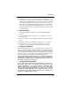
2.3 Connecting to a Network the NIC 2.3 Connecting to a Network the NIC Installing the Network Interface Card Chapter 2 Use an RJ45 connector (10/100BaseT) or BNC connector (10Base2) to connect to an Ethernet. 1. 2. Turn off the printer. Connect the connector to the NIC. Feritecore Tie band 10/100BaseT: 10Base2: Plug an RJ45 connector into the Use a BNC T adapter to connect 10/100BaseT port on the back of to the BNC connector on the back the NIC. Attach the ferrite core so of the NIC.
Chapter Utilizing Windows Programs 3 Utilizing Windows Programs Chapter 3
Utilizing Windows Programs Chapter 3
The CD-ROM contains the following programs for the Windows environment. • Discovery Program • Peer-to-Peer Printing Program This program provides peer-to-peer printing capabilities, without having to go through the server. Peer-to-peer printing can be enabled by installing IP peer-to-peer printing under a TCP/IP environment, or by installing IPX Peer-to-Peer printing program under an IPX/SPX environment.
3.1 Discovery Program Program –– Management Management Access AccessProgram Program(MAP) (MAP) Utilizing Windows Programs Chapter 3 3.1 Discovery Program – Management Access Program (MAP) – The Management Access Program (MAP) uses a Windows-based Web Browser linked with a proprietary bi-directional IPX/IP channel program to allow access to the NIC’s HTML-based monitoring and maintenance capabilities.
3.1 Discovery Discovery Program Program––Management ManagementAccess AccessProgram Program(MAP) (MAP) You can use the following procedure to manually install the MAP. 1. Insert the CD-ROM into your workstation’s CD-ROM drive. 2. Run the program. (In this example, we assume that drive D: is your workstation’s CD-ROM drive.) D:\Map\Setup.exe 3. Follow the instructions that appear on the screen. Chapter 3 The default installation directory is C:\Program Files\Map.
3.1 Discovery Program Program –– Management Management Access AccessProgram Program(MAP) (MAP) Note Utilizing Windows Programs Chapter 3 • The maximum hop value defines the maximum number of subnetworks the program will search to find a NIC. Setting a value 0 tells discovery program to search only within the subnet to which the workstation is connected. A hop value of 2 tells discovery program to search all networks accessible through as many as two routers.
3.1 Discovery Program – Management 3.2 IP Peer-to-Peer Access Printing ProgramProgram (MAP) 3.2 IP Peer-to-Peer Printing Program This section describes how to set up and use the IP Peer-to-Peer Printing program. With the setup procedure, you set up your print server ports for printing from a Windows environment. You can use the following procedure to manually install the IP Peer-toPeer Printing program. 1. Insert the CD-ROM into your workstation’s CD-ROM drive. 2. Run the program.
3.2 Discovery 3.1 IP Peer-to-Peer Program Printing – Management Program Access Program (MAP) Follow the instructions that appear on the screen. Utilizing Windows Programs Chapter 3 3. The default installation directory is C:\Program Files\IP-P2P. You can change to a different directory if you want. 3.2.2 Setting Up IP Peer-to-Peer Printing 1. 2. 3. 3-6 Click Start, point to Programs, and then point to IP-P2P. Click IP-P2P. This displays the setup dialog box.
3.2 IP Peer-to-Peer Printing Program Max Hops for Search: Type in a maximum hop value. The initial default value is 2. See the note under 3.1.2 Configuring the MAP for an explanation about maximum hops. IP Port Base: This is the starting port number for the printserver. The default is 10000 (corresponding to a TCP/IP port of 10001) but you can change it if you need to. Based on Serial Numbers Select this option to identify printers according to printer server serial number.
3.2 IP Peer-to-Peer Printing Program 3.2.3 Adding Printers for IP Peer-to-Peer Printing Utilizing Windows Programs Chapter 3 The following steps can be used to manually add a printer that cannot be found automatically due to router setup or the maximum hop count setting. Note, however, that manual addition of printer is normally not required. Step 1:Use P2P-IP to make the printer an IP peer-to-peer printer. 1. Click Start, point to Programs, and then point to IP-P2P. 2.
3.2 IP Peer-to-Peer Printing Program 4. Click the Find Printers button to automatically search the network for a printer as well as to register it. When registering a printer manually, enter the appropriate information for the following field descriptions and click the Add button. Field Descriptions IP Address: Type in the name you want to assign to the printer. Assign a name you feel best identifies the printer. Port Number: Type in the port number of the printer.
3.3 IPX Peer-to-Peer Printing Program 3.3 IPX Peer-to-Peer Printing Program Utilizing Windows Programs Chapter 3 The IPX Peer-to Peer Printing Program enables IPX Peer-to-Peer printing in a Windows 95 or Windows NT 4.0 environment. The following are the characteristics of IPX Peer-to-Peer printing. • IPX Peer-to-Peer printing implements peer-to-peer bi-directional printing between Windows workstations and NIC printers.
3.3 IPX Peer-to-Peer Printing Program If the NIC does not see any Novell activity, it will use 802.2 on 802.3 as a frame type and will assign itself a network number of 0. The frame type and network number being used is shown on the status report. Note Use the following procedure for an automatic installation of the IPX Peer-to Peer printing Program. If the opening screen does not appear as described in step 1, follow the instructions for the manual installation procedure. 1.
3.3 IPX Peer-to-Peer Printing Program 3.3.2 Installing the Printer Driver and Setting the Printer Port 1. Utilizing Windows Programs Chapter 3 2. 3. 4. Using the install program, install the printer driver that comes with the printer. Refer to the manual that came with the printer for details. Open the Properties menu item of the printer icon. Select the Detail tab. Select the port that you want from the Print to the following port item.
3.4 Using a Web Browser 3.4 Using a Web Browser Utilizing Windows Programs Chapter 3 Once you have assigned an IP address to your NIC, you can use a Web browser such as Netscape Navigator or Microsoft Internet Explorer to access the NIC’s onboard HTTP server. The HTTP server can be used to perform various maintenance procedures. See Appendix C of this manual for details.
Utilizing Windows Programs Chapter 3 3.
Chapter NetWare Configuration 4 NetWare Configuration Chapter 4
NetWare Configuration Chapter 4
4.1 Configuring NetWare 2.15 and 3.x Use this chapter if you will be printing from Novell NetWare. This chapter is divided into the following sections: • Configuring NetWare 2.15 and 3.x describes how to configure the NIC for use with Versions 2.15 or 3.x. Use PCONSOLE to set up the print server function. • Configuring NetWare 4.x in Bindery Emulation describes how to configure the NIC for use with Version 4.x —Bindery Services. Use PCONSOLE to set up the print server function.
4.1 Configuring NetWare 2.15 and 3.x When you are finished, turn the printer off and on again. The printer creates a status report that indicates the file servers to which the unit is attached and the queues which it services. Before you begin: • Verify that you have supervisor privileges on the file servers on which the NIC print server is to be entered. • Verify that your version of PCONSOLE is later than 1.0. NetWare Configuration Chapter 4 4.1.
4.1 Configuring NetWare 2.15 and 3.x 4.1.3 Enter the Print Server Name 3. Type the name of the print server into the entry box. The Novell print server name is printed under Novell NetWare information on the status report. Note • If desired, this name can be changed using MAP or Web Browser. The screen example shows how to enter the print server name for a print server with a serial number of MLT_160151. 4. Press Enter to add the print server name to the Print Servers list.
4.1 Configuring NetWare 2.15 and 3.x 4.1.4 Configure the Print Server NetWare Configuration Chapter 4 Use the following procedure to configure the Print Server’s function: 1. Choose the print server name from the Print Servers list and press Enter . The Print Server Information menu appears. 2. Choose Print Server Configuration from the menu and press Enter . 3. Choose Printer Configuration from the menu and press Enter . This displays the Configured Printers menu.
4.1 Configuring NetWare 2.15 and 3.x 8. Press Esc to return to the Print Server Configuration menu. 4.1.5 Assign Print Queues to the Printer When you assign queues to the defined printer, you authorize the print server to service these queues. Note • Do not assign the same queue to two different print servers. If a queue is assigned to multiple print servers, print jobs may not go to the intended printer. Choose Queues Serviced By Printer from the Print Server Configuration menu. 2. 3.
4.1 Configuring NetWare 2.15 and 3.x NetWare Configuration Chapter 4 4. 5. Select the queue you want and then assign a priority level from 1 to 10. It is recommended that you accept the default priority level. Press Enter . The queue appears on the list for the printer. Press Insert again to assign additional queues. When you finish assigning queues, press Esc and then save your changes. Continue to press Esc to return to the Print Server Configuration menu.
4.1 Configuring NetWare 2.15 and 3.x 4. 5. Insert to Set the First and Next intervals in the Notify Intervals screen. It is recommended that you use the defaults. The First interval is the number of seconds the network waits before it notifies candidates about a print job problem. The Next interval specifies how often in seconds candidates are notified. Enter a number for each interval and press Enter . Press Esc and then choose Save Changes.
4.1 Configuring NetWare 2.15 and 3.x 4.1.7 Installing the Print Server on Multiple File Servers NetWare Configuration Chapter 4 To install the print server on more than one file server, perform the procedures described in Sections 4.1.1 through 4.1.6 for each file server. You must use the same name and password for the print server (or no password) on all file servers. You set the password for the NIC using the MAP or a Web Browser (refer to 4.3 Configuring the NIC in Novell Directory Services).
4.1 Configuring NetWare 2.15 and 3.x 4.1.8 Primary File Server To use the primary file server option, use the following procedure on a file server close to the printer: 1. List the file servers to be serviced by the primary file server by selecting File Server To Be Serviced option from the Print Server Configuration Menu. 2. Press Insert to display the Available File Servers list. 3. Select the name if each file server to be serviced and press Enter to add it to the File Servers To Be Serviced list. 4.
4.2 Configuring NetWare 4.x — Bindery Emulation 4.2 Configuring NetWare 4.x — Bindery Emulation Novell’s NetWare 4.x can operate in two modes — Novell Directory Services (NDS) and Bindery Services Emulation. For Directory Services, see 4.3 Configuring the NIC in Novell Directory Services. These services run simultaneously and transparently to each other. The NIC may be configured to operate with Bindery Services mode only (this section), or to operate under NDS (4.
4.2 Configuring NetWare 4.x — Bindery Emulation Note • The command at the console prompt takes effect immediately. The definition in the autoexec.ncf file takes effect when the server is shut down and then restarted. 4.2.2 Configure in Bindery Mode with PCONSOLE Once you confirm the server has Bindery Context, use the following procedure to configure the NIC. 1. Log into the network as ADMIN. 2. Type PCONSOLE and press Enter . The following screen appears.
4.2 Configuring NetWare 4.x — Bindery Emulation NetWare Configuration Chapter 4 Use Quick Setup to connect your print server, print queue and printer correctly. You can modify these later if you need to. 5. 6. Select Print server and press F3 to modify the entry. Type the name of the print server in the Print server field and press Enter . Note • The print server name is printed under the Novell Network Information on the status report. The factory default name is MLT_. 7.
4.3 Configuring the NIC in NetWare 4.3 Configuring the NIC in Novell Directory Directory Services Services The Directory Information Base (DIB) is used to store information about servers and services, users, printers, gateways, etc. It is a distributed database, allowing access to data anywhere on the network wherever it is stored. Pre-4.x NetWare versions provide the same data found in the DIB but the data is stored in the NetWare Bindery.
4.3 Configuring the NIC in NetWare 4.3 Directory Configuring the NIC in Novell Directory Services Services NetWare Configuration Chapter 4 You may use NWADMIN to configure the printer in NDS. Prior to printing, NDS must be set up as follows and the NIC must be set up with NDS Context and Tree. See Section 4.4. The steps below describe the use of NWADMIN configuration to create printer, print server, and print queue objects. Then, you will assign, or associate those objects with each other.
4.3 Configuring the NIC in NetWare 4.3 Configuring the NIC in Novell Directory Directory Services Services When the New Object window appears, scroll down the Class of New Object icon list, select the Printer icon and click on the OK button. 4. When the Create Printer window appears, type a value in the Printer Name field and click on the Create button. 4.3.2 Create Print Server Object 1. 2. 3. Again, highlight the Organizational Unit, select the Object item from the menu and choose Create...
4.3 Configuring the NIC in NetWare 4.3 Directory Configuring the NIC in Novell Directory Services Services 4.3.3 Create Print Queue Object 1. 2. NetWare Configuration Chapter 4 3. Once again, highlight the Organizational Unit, select the Object item from the menu and choose Create... At the New Object window, scroll down the Class of New Object icon list, select the Print Queue icon, and click on the OK button.
4.3 Configuring the NIC in NetWare 4.3 Configuring the NIC in Novell Directory Directory Services Services 4.3.4 Assign Printer Object 1. Go to the Directory Tree. Double click on the printer object just created and bring up the Printer window. See below. Find the Assignments button on the right-side of the window and click on the Add button. 4-17 NetWare Configuration Chapter 4 Click on the object (hard drive) of your choice and it will appear in the Selected Object: field. Click on the OK button.
4.3 Configuring the NIC in NetWare 4.3 Directory Configuring the NIC in Novell Directory Services Services When the Select Object window appears, find the print queue object just created among the choices listed in the Objects box and select it. NetWare Configuration Chapter 4 2. Click on the OK button and the print queue just created is added to the Print Queues: box in the Printer: window. Click on the OK button again.
4.3 Configuring the NIC in NetWare 4.3 Configuring the NIC in Novell Directory Directory Services Services 4.3.5 Assign Print Server Object At the Directory Tree, double click on the print server object you just created and bring up the Print Server window. 2. At the Print Server: window, click on the Assignments button and Add button to bring up the Select Object window. Select the printer object just created from the Objects: box and click on the OK button.
4.3 Configuring the NIC in NetWare 4.3 Directory Configuring the NIC in Novell Directory Services Services 4.3.6 Check Assignments NetWare Configuration Chapter 4 At the Directory Tree, double click on the Print Queue object you just created. At the Print Queue window, click on the Assignments button. If you configured the print queue and printer correctly they will appear in the proper boxes on the Print Queue window. Press the Cancel button.
4.3 Configuring the NIC in NetWare 4.3 Configuring the NIC in Novell Directory Directory Services Services 4.3.7 Set Up and Reset the Printer NetWare Configuration Chapter 4 NWADMIN configuration is complete. Before you can begin printing, though, be sure to set up and reset (power cycle) the printer.
4.4 NIC Configuration 4.4 NIC Configuration NetWare Configuration Chapter 4 The MAP or a Web Browser must be used to define the context and tree of the Print Server. It is also used to change the Print Server name, set in a password, modify scan and frame search parameters, and sent in bindery-mode specific values. Use the MAP or Web Browser (refer to Chapter 3) to access the Setup pages of the NIC. Once you have accessed the Network Setting pages or the Main Menu, do the following: 1.
4.4 NIC Configuration 6. If the Print Server is to be operated under Novell Directory Services, type in a Context entry and Preferred NDS Tree entry in the appropriate fields. Be sure to give the whole context, whether typed or typeless, and do not begin your context path with a trailing period (.). If you don’t know your tree, type: whoami at the DOS command line. A typed context name example is: ou=standard.
4.5 Using the Novell PCONSOLE Utility 4.5 Using the Novell PCONSOLE Utility This section explains how to use the PCONSOLE utility to perform the following tasks: • Attach and select a file server • Select or delete queues for the print server • Set-up the Notify function See the NetWare Print Server Manual for detailed information on this utility. Note NetWare Configuration Chapter 4 • You must have Supervisor privileges to perform many PCONSOLE operations. 4.5.
4.5 Using the Novell PCONSOLE Utility 4.5.3 How to Set Up Notify You can specify users or groups of users that are notified if a problem occurs when a print job is sent to the printer. If the print server is servicing queues on multiple file servers, you must set up a NOTIFY list for each file server. To set up NOTIFY, use the following procedure: 1. Start the PCONSOLE utility. 2. Select Print Server Information from the Available Options menu. 3. Select the print server from the menu. 4.
4.5 Using the Novell PCONSOLE Utility Select Notify List for Printer from the menu. Select the printer from the Defined Printers menu. Press Esc at the File Server/Notify Name/Notify Type/First/ Next screen. The Notify Candidates screen appears. 8. Select the user or user group from the Notify Candidates screen. The Notify Intervals screen displays. 9. Set the First and Next intervals for notifying users about printer problems.
Chapter AppleTalk Configuration 5 AppleTalk Configuration Chapter 5
AppleTalk Configuration Chapter 5
5.1 Choosing the Printer Use this chapter if you will be printing from a Macintosh. This chapter explains how to configure the NIC using AppleTalk and how to use the AppleTalk NIManage utility program. Note • The printer must be equipped with the PS option when operating in an AppleTalk environment. Note • The Chooser screen will not show AppleTalk zones if your network does not have more than one zone. 8. 9.
5.2 Loading the AppleTalk NIManage Utility Program 10. The options available at this point depend on your printer driver. With a typical driver, you may select SETUP. Then select AUTO SETUP. There will be a series of messages as the Chooser communicates with the printer and locates the proper PPD. The setup screen will return, listing the PPD file selected. Select OK. Then exit from Chooser. 5.
5.2 Loading the AppleTalk NIManage Utility Program You can use the following procedure to start the NIManage program instead of step 1 to 5 above. Insert the CD-ROM into the CD-ROM drive, and double-click the APPLTLK folder from the CD-ROM. Double-click the NIManage icon • The Zone and Device screen appears on the display. Chapter 5 • • If you have one zone, the above screen will not appear. 6. From the Device display panel, select the NIC.
5.3 Configuring the NIC 5.3 Configuring the NIC You use the options added to the menu bar to configure the print server. Depending on your printer, certain operations may not be available. These functions will be “grayed” out and cannot be selected. 5.3.1 Configuration Use the Configuration function to change the names of the device and AppleTalk Zone. AppleTalk Configuration Chapter 5 5.3.2 Error Log The Error Log function is used to view a log of events that the NIC has registered.
5.3 Configuring the NIC 5.3.3 Protocol Setup Use the Protocol Setup option to configure network protocols other than AppleTalk. Selecting the Protocol Setup function displays the following screen: 1. 2. 3. 4. Click the protocols to On if you want them to be active. Click those protocols that you do not want to use to Off. The utility will not let you make active any protocol that the NIC does not support or cannot handle because of active protocol limitations.
AppleTalk Configuration Chapter 5 MEMO
Chapter TCP/IP Configuration 6 TCP/IP Configuration Chapter 6
TCP/IP Configuration Chapter 6
6.1 Installation in a Windows Environment This chapter explains how to configure the NIC and your network for use with TCP/IP communication in various environments. Independent setup and installation procedures are provided for Windows systems and for most popular UNIX systems. The NIC TCP/IP capability will also operate with lpr spoolers on other systems, and with spooler/ supervisor capabilities that communicate raw print jobs to the Print Server TCP/IP Port.
6.1 Installation in a Windows Environment Note • See the documentation that comes with Windows for details about installing TCP/IP on each workstation. • Printing with TCP/IP requires that the workstation have TCP/IP capability and the corresponding spooler, lpr; or that the workstation can share an lpr queue on a Windows NT server (for example) that has one. In general, if printers are not shared, an lpr queue must be created on each workstation from which printing is initiated.
6.1 Installation in a Windows Environment Windows lpr Spooler Version 4.1 (wlprs41.zip and wlprspl.txt) for the lpr. See the file named wlprspl.txt for details about installing Windows lpr Spooler Version 4.1. If you wish to use the BOOTP, you also need the BOOTPL32.exe file provided with this NIC. Windows NT Windows NT (version 3.5 or higher) does come with TCP/IP and lpr capabilities, although these must be installed when the unit is configured.
6.1 Installation in a Windows Environment 6.1.1 Setting up the NIC The NIC must be given IP address and routing information to be used with TCP/IP. This can be done with MAP if you have a NetWare connection on your network, or with AppleTalk NIManage for Macintosh utility program if there is an Apple Macintosh on the network. Follow the instructions for these programs which are documented elsewhere in this manual. If you cannot use these programs, you can use either the ARP procedure or the BOOTP.
6.1 Installation in a Windows Environment For example: >arp -s 192.9.200.200 00-20-6b-aa-bb-cc >ping Request should time out. For example: >ping 192.9.200.200 3. 4. Recycle the power on the printer, or let the NIC reset itself. The NIC will produce a status report that should include the entered IP address. When the NIC is up again, type the following at the command prompt: >ping (continue until you get a reply) Note BOOTP programs use the BOOTP protocol.
6.1 Installation in a Windows Environment BOOTP programs are located on the CD-ROM in the directory named bootp. 5. Copy BOOTPL16.exe or BOOTPL32.exe into a directory on 6. your workstation’s hard disk. Reset the printer. Note • The NIC issues the BOOTP request for a finite period of time. The NIC must be freshly reset for this program to work. Run the program. Pull down the Admin menu to Configure option.
6.1 Installation in a Windows Environment 6.1.4 Setting Up IP and lpr Parameters The NIC provides for a setup connection via the standard Telnet port. To be able to make changes to a unit with factory default settings, you must logon as “sysadm”. The default password is also “sysadm” (This password can be changed from the Telnet utility). Section 6.3 Running Telnet, describes the use of the Telnet utility. 1. Telnet to the NIC (the login and password are both sysadm). 2.
6.1 Installation in a Windows Environment Windows 95 Once you install the spooler onto the workstation; the setup program will create a group and icon. 1. Double click on the spooler icon. 2. Click on setup, define new queue. 3. At the Remote Host Name prompt type the NIC’s IP Address, and for the Remote Printer Name enter PORT1. 4. Using the install program, install the printer driver that comes with the printer. Refer to the manual that came with the printer for details. 5.
6.1 Installation in a Windows Environment 6-9 TCP/IP Configuration The following procedure is used to set up the lpr spooler on the Windows NT server. 1. Using the install program, install the printer driver that comes with the printer. Refer to the manual that came with the printer for details. 2. Open the Printer Properties dialog box for the printer. Click Ports to display the Ports property tab. 3. Click Add Port. The available port types are displayed. 4. Select LPR Port and click New Port.
6.2 UNIX Printing 6.2 UNIX Printing Note • This manual cover general settings only. See your UNIX system manual for full details about setting procedures. The NIC can support UNIX TCP/IP printing in two modes: • Host-based lpd where a supplied line printer daemon is running on one or more workstations and print data is communicated to the NIC via a TCP/IP port or, • Printer-based lpd where the printer appears as a host running a line printer daemon.
6.2 UNIX Printing Between the host-based and printer-based TCP/IP printing capabilities, the NIC works with: • All UNIX systems that support lpd • System V Rel. 4 (on 386 platforms) • DEC ULTRIX RISC Versions 4.3 and 4.4 • DEC OSF/1 Versions 2.0 and 3.0 • Solaris: Version 1.1.3 (SunOS 4.1.3), Version 2.3 (SunOS 5.3), Version 2.4, and Version 2.5 • HP-UX Series 700 and 800 Version 9.01 and Version 10.0 • IBM AIX Version 3.2.5 • SCO UNIX Version 3.
6.2 UNIX Printing 6.2.1 Configuring the IP Address on the NIC Regardless of the printing mode selected, the NIC must be given IP address and routing parameters. You can configure the IP address for the NIC in one of the following ways: • Use MAP, as described in Chapter 3. • Use AppleTalk NIManage utility program, as described in Chapter 5. • Use the BOOTP (Bootstrap Protocol). • Use the RARP (Reverse ARP) capability (Ethernet II frame type only). • Use arp and ping capability.
6.2 UNIX Printing 4. Edit the hosts file (usually /etc/hosts) or use NIS or DIS to add the IP address and NIC’s node name. See the network administrator for the IP address. For example, you would type in the following for NIC named printfast with an IP address of 192.9.200.200: 192.9.200.200 printfast 5. 6. Stop the BOOTP daemon if it is running.
6.2 UNIX Printing 8. Check the printer to verify that the NIC is connected to the network. Turn on the printer. 9. Wait until the printer powers up and finishes initializing to allow enough time for the IP address to become known and to be saved in NVRAM. The NIC should reinitialize itself. 10. After the NIC has been reinitialized, send a ping command to verify that the print server obtained its IP address. For example: #ping 192.9.200.
6.2 UNIX Printing 5. Edit the /etc/ethers file or use NIS or DIS to add the MAC Address. To continue the example, for the printfast card with an MAC Address of 00:20:6b:aa:bb:cc: 00:20:6b:aa:bb:cc printfast 6. 7. 8. 9. If the rarp daemon is running, stop it and restart it. Verify that the daemon is running. Check the printer to see that the print server is connected to the network. Turn on the printer.
6.2 UNIX Printing 4. Edit the hosts file (usually /etc/hosts) or use NIS or DIS to add the IP address and print server’s node name. See the network administrator for the IP address. For example, you would type in the following for a NIC with a name of printfast and an IP address of 192.9.200.200: 192.9.200.200 printfast 5. Add an entry to the arp cache for the Print Server’s IP address and MAC Address. For example: #arp -s 192.9.200.200 00:20:6b:aa:bb:cc 6. 7.
6.2 UNIX Printing 6.2.2 lpd Printing lpd is an implementation of the standard UNIX line printer daemon which lets you print across a TCP/IP network without the need to install software on your workstation with all filtering and banners done by NIC. Remote printing uses the same commands (lpr, lpq, lpc) as local printing. The process begins when the lpr call finds a printer on a remote system by looking at the remote (rm) entry in the /etc/printcap file for that printer.
6.2 UNIX Printing 1. Open the /etc/printcap file. Make an entry naming the NIC as the remote host and PORT1 as the remote printer name.
6.2 UNIX Printing 6. When a window appears, change the values shown to configure the NIC. The values displayed are default values. You must replace the short and long form filter values with the values shown below.
6.2 UNIX Printing Installation is complete. Test your printer by executing the following command: #lp -d 6.2.2.4 Setting Up an HP/UX Remote Printer to Use lpd Set up a remote printer on the host that sends jobs to a NIC using the NIC lpd. 1. At the prompt, type: #sam 2. 3. 4. 5. 6. When a window appears, select Printer/Plotter Manager. When the menu appears, select List printer and plotters. When a list appears, select Actions in the title bar.
6.2 UNIX Printing 6.2.2.5 Setting Up an AS/400 Systems to Use lpd When working with the output queue description (WORKOUTQD), there are several fields that must be defined for the NIC to function properly as a remote printer device. When prompted for the remote system, type INTNETADR so the AS/400 recognizes the device as an IP device. 12. Type PORT1 13. Connection type must be IP. 14. Internet address must be the IP address of the NIC. 15. Destination type must be OTHER. 16.
6.2 UNIX Printing 11. Your configuration is displayed. You are asked whether these values are final. Type Y or N and press Enter . An example is shown below. Printer #7 Symbol Type Representative Value lp (line printer) STR rm (remote host) STR rp (remote printer) STR PORT1 sd (spooler directory) STR /usr/spool/lpd7 12. Add comments to the printcap file. For example, you can type: Dick’s printer down the hall Enter 13.
6.2 UNIX Printing 7. 8. Confirm the information you have entered. Type: Y Confirm the preceding connection as your system default. Type: Y 9. Enter another printer name or quit setup. Type: Q 10. “Do you want to start the remote daemon now?” Type: Y 11. Using a line editor of your choice, edit the /etc/printcap file by changing the :rp= entry to PORT1.
6.2 UNIX Printing 3. At the prompt, type: #lpadmin -p -s !PORT1 Note • There is no space after the remote host name. 4. At the prompt, type: #enable #accept 6.2.3 Installing TCP/IP for NIC If Not Running lpd TCP/IP Configuration Chapter 6 The CD-ROM provided with the NIC includes install scripts for various UNIX systems.
6.2 UNIX Printing 6.2.3.1 Loading the Software The following procedures are only necessary when using the supplied host-based lpr capability. Loading the software is not necessary if printer-based lpr is used. 1. Log in as superuser (root) to the system that spools directly to the print server. 2. Insert the CD-ROM in the host drive. 3. Go to or create the directory in which you want to install the software.
6.2 UNIX Printing 6.2.3.3 Manual Selection of Filters The NIC ships with an input filter called psfilter and an output filter called psbanner to print PostScript banners. You may wish to change infilter or outfilter entries in the /etc/printcap file. The following is a sample printcap entry using these filters: | NIC printer:\ :lp=/dev/nic/:\ :if=/usr/nic/psfilter:\ :of=/usr/nic/psbanner:\ :sd=/usr/spool/: 6.2.3.4 Installing and Printing on Solaris 1.
6.2 UNIX Printing 5. “Is this printer PostScript?” Type yes or no and press 6. Enter . The script creates a printcap entry for the printer just configured. The screen displays the entry and asks if you want the script to append it to your /etc/printcap file. See below for a sample printcap file. Type yes or no and press Enter . If you type no, you may perform manual edits. In your /etc/printcap file, be sure not to change the name of the device given NIC in Step 2.
6.2 UNIX Printing 11. Installation for the system is done. You are prompted to configure any more printers. Type yes or no and press Enter . We also suggest you ping the NIC to test communications. 6.2.3.5 Installing & Printing on an DEC ULTRIX 4.3 RISC System 1. Run the Installation script by typing: #nicinst The script automatically downloads the correct NIC utilities for your particular system and prompts you for information as needed. 2.
6.2 UNIX Printing 6. The script creates a printcap entry for the printer just configured. The screen displays the entry and asks if you want the script to append it to your /etc/printcap file. See below for a sample printcap file. Type yes or no and press Enter . If you type no, you may perform manual edits. | NIC printer:\ :lp=/dev/:\ :if=/usr/nic/infilter:\ :sd=/usr/spool/: 7. Installation for the system is done.
6.2 UNIX Printing 4. “What is the printer name?” Type the desired printer name and press Enter . Your screen will now display the information you provided to the install script. For example: Node name of the NIC: printfast Printer name to be used: The printer is attached on: PORT 1 5. You are asked to OK this configuration. Type yes or no and press Enter . The script starts the daemon for the newly configured printer automatically.
6.2 UNIX Printing When using sam, specify everything as if the printer were directly connected to /dev/lprprinter/. The software installed with your HP system can satisfy most of your printing needs. HP supplies ASCII-to-PostScript filters and the system will invoke them automatically if you define the content type of the printer as PostScript. The HP/UX lp system also supplies interface scripts that produce PostScript banners.
6.2 UNIX Printing Note • Use of this default interface in most cases will suffice for generic or routine printing of most PostScript, PCL, and ASCII files. In order to utilize a printer specific interface other than the default interface script (named standard), you must have a copy of that printer interface edited and installed in the /usr/nic directory. Next, you will need to edit the printer interface program you created in step 3. 4.
6.2 UNIX Printing Note • lpadmin configures the printer name and associates it with a given device and printer interface program. There is no /etc/printcap file involved with this method of configuration. 8. Next, you need to initialize the printer Type the following commands: #accept #enable Note • After each entry, lpadmin should provide an acknowledgment of the command invoked. 9.
6.2 UNIX Printing 2. Select your system. Choose one from these options: 1) AT&T/SVR4; 386 2) SCO UNIX System V 3) None of the above Type 1, 2, or 3 and press 3. Enter . “What is the node name of the NIC?” Type the name assigned in the /etc/hosts file and press For example: Type printfast and press Enter . 4. . “What is the printer name for this NIC-linked printer?” Type a printer name and press 5. Enter Enter . Your screen will now display the information you provided the install script.
6.2 UNIX Printing The SCO UNIX lp system uses the lpadmin maintenance command to configure a printer (there is no /etc/printcap file). The specific commands to do this are: #lpadmin -p -v /dev/nic/ Note • Your host may require you to specify the model by using the -i command. #enable #accept You can also use other options for the lpadmin command. See your system documentation for details.
6.2 UNIX Printing An AIX virtual printer is simply a high level software view of a data stream, queue, and device that controls how a given job will be processed. A different virtual printer should be defined for each data stream that a real printer supports. For example, you would use different virtual printers for PostScript and PCL jobs even though they are destined for the same physical printer.
6.2 UNIX Printing 6. Shut down the qdaemon using the command #stopsrc -s qdaemon 7. 8. Edit /usr/lpd/qconfig to change the special file for device from /dev/ to /dev/nic/ . Restart the daemon with: #startsrc -s qdaemon The installation script then will create the named pipe and starts the supplied print daemon using the printer name and NIC information you supplied.
6.2 UNIX Printing Output spooled on the virtual printer as defined above, will now be sent to the named pipe and routed to NIC. Before you edit the files above, be sure that the following daemon is running: /usr/nic/lpr_print /dev/nic/ printfast 10001 & 6.2.3.9.2 AIX Print Commands The AIX lp command works slightly differently than the lp command for other System V Release 4 systems.
6.3 Running Telnet 6.3 Running Telnet The Telnet utility uses the standard remote terminal protocol to configure the IP address, lpd printers, and other parameters on your system. Use the following guidelines to run Telnet. You have the same functionality with the HTML pages accessed by MAP or a Web Browser, as described in Chapter 3. • Most often, you make selections from menus by toggling between one choice or another, by selecting/deselecting or enabling/disabling an item.
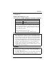
6.3 Running Telnet The Configuration Utility Unit Serial no. 460121 V5.04 Main Menu 1. 2. 3. 4. 5. 6. E. 4. IP Parameters LPD Printers Protocols Reset Unit Restore Factory Defaults Change Password Exit To end your Telnet session, type E at the Main Menu. If you have made any changes you are prompted to either Save Changes and Exit or Exit Without Saving Changes. Choose your option and press Enter . Note • Press ? to access the Telnet help utility. Chapter 6 6.3.
6.3 Running Telnet 2. Type 1 again and press appear: Enter . The IP Address submenu will The Configuration Utility Unit Serial no. 460121 V5.04 1. 2. 3. 4. 3. 4. IP Address 192.9.200.200 Subnet Mask 255.255.255.0 Default Gateway 199.9.200.254 Base Port Number 10000 Enter a new IP Address and press Enter . Repeat the previous steps to change Subnet Mask and Default gateways. Enter 4 to change the base port number.
6.3 Running Telnet Print Server Setup Job Detected to be 1. Action PCL ASCII changed to not PostScript PostScript Job discarded PostScript ASCII PostScript header added, changed to PCL, PS, ASCII any no action To access the LPD Printers menu, type 2 and press Enter . For a unit at factory default, the menu shown below appears. LPD Printers 1. Printer 1 2. Banners 2. To change the set of emulations, type 1 and press options shown below appears.
6.3 Running Telnet 6.3.4 Enable/Disable Network Protocols To enable network protocols, at the Main menu type 3 and press Enter . You are given the choice of disabling either NetWare or AppleTalk. 6.3.5 Reset Unit In order to reset the NIC, type 4 into the main menu and press the keyboard. Enter on Note that resetting the NIC initializes the network interface without effecting the printer interface. 6.3.
6.3 Running Telnet 6.3.8 Exit Telnet Use the following procedures to exit Telnet: 1. To end your Telnet session, type E at the main menu. If you have made any changes, the following menu appears: The Configuration Utility Unit Serial no. 460121 V5.04 Exit 1. Save Changes and Exit 2. Save Changes and Reset 3. Exit Without Saving Changes Choose your option and press Enter . For example, type 2 and press Enter . The program saves your changes and resets the print server so that the changes take effect.
6.4 FTP Printing 6.4 FTP Printing Use the following procedure for using FTP (File Transfer Protocol) to print. 1. Start up the FTP client and look into the print server card using the following setting. Host Name: Login Name: Password: Upload (PUT) the file you want to print. The printer prints the uploaded (PUT) file. Note • FTP Printing does not support selecting multiple file names. • Only one person can be logged on to a port at any particular Chapter 6 time. TCP/IP Configuration 2. 3.
6.5 Dynamic Host Configuration Protocol 6.5 Dynamic Host Configuration Protocol TCP/IP Configuration Chapter 6 DHCP is a service much like bootp that provides a method for assignment and maintenance of IP addresses. The NIC is able to obtain IP information from this service. There are two user settable variables related to the DHCP function. These are accessible in the TCP section of Network Administration, in the HTML pages. 1. DHCP enable; and 2. Use IP info in NVRAM a.
Chapter Operation and Troubleshooting 7 Operation and Troubleshooting Chapter 7
Operation and Troubleshooting Chapter 7
7.1 LED Status Indicator The NIC has two LED status indicators: amber and green. The amber LED generally indicates job activity; it flashes when a print job is being communicated to the NIC; it is off when no activity is occurring. The green LED indicates the operating condition of the NIC when it is powered on during normal operation. The following table provides the conditions that this LED may indicate. LED Patterns And the printer is... Then The NIC... Operating Condition First powered on.
Operation and Troubleshooting Chapter 7 7.1 LED Status Indicator LED Patterns Green LED blinks slowly. Green LED blinks rapidly. Green LED alternately blinks with amber indicator. 7-2 And the printer is... Then The NIC... Operating Condition Awaiting print jobs sometime after power-on completes. Some printer interface error. Error Awaiting print jobs. Has lost its NetWare connection to file server. Error Finished with power-on sequence. Has been reset to factory defaults.
7.2 Status/Configuration Report It is strongly recommended that you review this report immediately after installation and any time the setup has been changed. If the report does not include a protocol that was configured, check that the procedure was done properly. Unit Serial No: 460121 Version: 02.
7.2 Status/Configuration Report Chapter 7 AppleTalk Network Information enabled Frame Type: 802.2 SNAP On 802.
7.3 Resetting the NIC to Factory Default This process is called “Reset to Factory”. It can be done with the standard Telnet or Web pages (accessed via MAP or a Web Browser) utility. However, if network access is not possible, the following method may be used. Note • Resetting to factory default means that the print server loses all data such as names and IP addresses. It does not lose its serial number and MAC Address.
7.4 How to Diagnose Problems Operation and Troubleshooting Chapter 7 7.4 How to Diagnose Problems Use the following list to determine the cause of printing problems: 1. Verify that the printer is functioning properly. • Is the printer printing? Make sure the printer is operating properly by causing it to generate a test page. See your printer's owner's manual for instructions on generating a test page. • Is the printer on-line? Verify that the printer is on-line or else nothing will print.
7.5 Troubleshooting Checklists 7.5.1 Troubleshooting Network Hardware Connections Be sure that the NIC has properly selected the connector type that you are using. • Check that the network connector is plugged into the RJ connector on the NIC. • Try another cable to make sure you do not have a bad cable. If you are using a 10BaseT concentrator hub that does not support the link signal, use Manual Ethernet Port selection instead of the factory default or the Automatic Ethernet Port selection.
7.5 Troubleshooting Checklists Did you assign the printer to the type Remote Other /Unknown? If the PCONSOLE settings are correct, the connection between the printer and network may have been broken. Turn the printer off and, using PCONSOLE, wait for the status message Not Connected. Turn the printer on and the status should change to Waiting for Job. Operation and Troubleshooting Chapter 7 • 7.5.2.
7.5 Troubleshooting Checklists Is AUTO ENDCAP enabled? Chapter 7 Auto Endcap lets you send data to a network printer. Use PRINTCON to check. If not, enable it. 7.5.2.4 NIC Configuration Checklist If all your hardware connections are correct, check the following: • Use MAP to check the status of the print server. The Report Print Server Status screen shows the status for the selected NIC.
Operation and Troubleshooting Chapter 7 7.5 Troubleshooting Checklists • The password assigned to the NIC through PCONSOLE matches the password assigned through MAP Program. Use MAP to update the password stored in the network Print Server’s memory. • The print job is in the print queue and waiting to be printed. Use PCONSOLE to check if the print jobs are being sent to the printer. 7.5.2.
7.5 Troubleshooting Checklists 7.5.3 Troubleshooting AppleTalk Protocol • Is the Macintosh computer connected to the network through Ethernet, and, has the Macintosh AppleTalk driver been selected? Go to the Control Panel, then go to Networks to check. • Did you select the correct NIC and correct zone? • Is AppleTalk enabled on the Macintosh? Use Chooser to check this.
Operation and Troubleshooting Chapter 7 7.
Appendix Jumper Settings A Jumper Settings Appendix A
Jumper Settings Appendix A
Jumper Settings HANDLING PRECAUTIONS FOR STATIC SENSITIVE DEVICES The Network Interface Card is normally contained within the printer which acts to protect sensitive components from damage due to electrostatic discharge (ESD) during normal operation. When performing installation procedures, however, take proper static control precautions to prevent damage to equipment. Make sure you do not have the printer plugged into a wall outlet. If it is, unplug the power cord BEFORE you open the unit.
A.1 Network Interface Cards and Jumper Locations The illustration below shows the location of each of the jumpers on the Ethernet NIC. TEST BYPASS FACT P.ACK T.B. ON ON Jumper Settings CS1 JP2 OP1 OP6 OP2 OP3 OP4 OP5 OP7 Appendix A A.1 Network Interface Cards and Jumper Locations CS2 10/100BaseT OP1 OP6 CUS P.W. S.R. OFF OFF CS1 JP2 TEST BYPASS FACT P.ACK T.B. ON ON AUTO MAN JP3 JP4 10BT THIN CS2 10BaseT/2 Note • The shaded areas indicate the default pin positions.
A.2 Reset to Factory Default If the unit is powered up with a jumper in the OP2, the board will go into a “reset all parameters to Factory Default” state. This will be indicated by the three quick green flashes followed by the alternating red and green indications (once per second rate). This special indicator sequence means that the NVRAM parameters have been reset to factory default values. Now turn off power and shift the OP2 jumper to the default position.
Jumper Settings Appendix A A.
Appendix Specifications B Specifications Appendix B
Specifications Appendix B
B.1 Network Interface Card B.1 Network Interface Card The following tables provide general specifications for the NIC. 125.00 mm length × 95 mm height Weight: 10Base T/2 : 3 10/16 oz. (102.5 g) 10/100 Base T: 3 3/16 oz. (89.5 g) Environment: 0 to 50 degrees Centrigrade, 5% to 80% humidity Controls and Indicators: One green LED and one amber LED Configuration: Stored in non-volatile memory Connectors: Ethernet: 8-wire RJ45 10/100BaseT or BNC 10Base2 B.
Specifications Appendix B MEMO
Appendix Using a Web Browser C Using a Web Browser Appendix C
Using a Web Browser Appendix C
C.1 Accessing the HTTP Server Screens The NIC and printer have an onboard HTTP server, so a standard Web browser can be used to make printer status monitor and network related settings. For details, see the PageScope Light User’s Manual. C.1 Accessing the HTTP Server Screens Perform the following steps to access the HTTP Server screens from your browser. 1. Start up your browser. 2. Enter the URL below: http:// 3. The top page that is shown below will appear on your monitor..
C.1 Accessing the HTTP Server Screens Menu Options System Displays various information regarding the configuration of the printer including options, trays and memory capacity. Job Info Allows you to manage the print jobs that are being processed by the printer. Printer Allows you to specify all of the basic settings of the printer. Network Allows you to specify all of the basic settings of the NIC. Using a Web Browser Appendix C Note • The contents of this manual explain the settings of the NIC only.
C.1 Accessing the HTTP Server Screens C.1.1 Network page Note • Depending on the version of the utility you are using, the appearance of the screen may differ from that shown above. Click on a link to jump to the corresponding page, where you can make the settings indicated by the link text. Of course, you can also use the navigation features (Back, Forward, etc.) of your Web Browser to move between screens.
C.1 Accessing the HTTP Server Screens Important! • To change network settings you must first type the correct password (same as the management password) in the password field provided. • Clicking a button to execute a network setting change operation while the wrong password is in the password field causes the password error screen to appear, without changing the setting. C.1.1.1 Reset Use this screen when you need to reset the NIC to allow newly set parameter values to take effect.
C.1 Accessing the HTTP Server Screens Your password can contain letters, numbers, and punctuation. Note that the password is case-sensitive, which means that the system distinguishes between upper-case and lower-case letters. C.1.1.6 Setup NetWare This screen is for making NetWare environment settings. See Chapter 4 NetWare Configuration for details on configuring NetWare. C.1.1.7 Setup TCP/IP This screen is for making TCP/IP environment settings.
C.2 Supported Web Browsers C.1.1.11 Unit info This screen shows you the version of your Network Interfacecard. Clicking on the Unit Serial Number jumps to the Network Address screen. C.1.1.12 Language This network card supports the following language modes. • French • UK-English • Italian • German • Dutch The default language mode is US-English. To change to another language mode, click the Language menu item and select the mode you want on the screen that appears.
Appendix Index D Index Appendix D
Index Appendix D
Index 10/100BaseT 1-1, 2-2, A-2, B-1 10Base2 1-1, 2-2, A-2 E 7-1, 7-11, A-2, B-1 F 6-37 AppleTalk 1-1, 5-1, C-5 Choosing the Printer 5-1 Configuring C-5 NIManage 5-1 Troubleshooting 7-11 Zone 5-1, 5-4 arp & ping 6-4, 6-15 AS/400 Setting Up 6-21 ASCII 6-32, 6-41 Electrostatic Discharge A-1 Ethernet 2-2, 4-23, 6-4, 6-12, H I Factory Default A-3, C-4 Reset 6-43, 7-5 FTP 6-45 Printing 6-45 printing 1-1 HP/UX System Installing 6-29 Setting Up 6-20 HTTP server 3-13, C-1 IP Address 3-7, 3-13 Assigning 5-5
Index J Index Appendix D L M Jumper Locations A-2 Settings A-1 Language 6-41, C-6 Select 6-41 LED Status Indicator 7-1 lpd Printing 6-17 AIX 2.5 6-18 AIX System 6-18 AS/400 Systems 6-21 BSD 6-17 HP/UX System 6-20 SCO UNIX 6-22 Solaris 2.X 6-23 System V Rel.
Index R S OSF1/ALPHA 6-21 Installing 6-26 Setting Up 6-21 OTS Multiprotocol 5-1 PageScope utility C-1 Password C-4 Change 4-8, 6-43 Factory default 3-2, 6-7, C-3 PCL 6-32, 6-41 Peer-to-Peer Printing 1-1, 3-1 IP 3-1 IPX 3-1, 3-10 PostScript 6-32, 6-41 printcap file 6-10, 6-17, 6-18 Printer Powering Up 2-1 Preparing 2-1 Test C-5 Printer Management page 3-4 PS option 5-1 System V Rel.
Index U Unit info C-6 UNIX arp & ping 6-15 BOOTP 6-12 RARP 6-14 UNIX Printing 6-10 AIX 2.5 6-18 AIX 4.