Linear Industries, Inc.
AT71-250 Transmitter Owner’s Manual User Notices and WARNINGS USER NOTICES IT IS VERY IMPORTANT TO READ THIS MANUAL PRIOR TO OPERATION OF THIS TRANSMITTER! Notice 1 The transmitter main operating voltage setting is marked on the rear of the AT71-250 chassis. Notice 2 The transmitter operating frequency is set from the factory. Notice 3 For adjusting the RF output power setting a qualified technician should always employ the use of an RF Wattmeter and a calibrated dummy load.
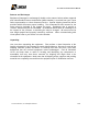
AT71-250 Transmitter Owner’s Manual WARNING! THE VOLTAGES AND CURRENTS IN THIS EQUIPMENT ARE DANGEROUS. PERSONNEL MUST, AT ALL TIMES, OBSERVE SAFETY WARNINGS, INSTRUCTIONS, AND ANY LOCAL REGULATIONS. THIS OWNER’S MANUAL IS INTENDED AS A GENERAL GUIDE FOR TRAINED AND QUALIFIED PERSONNEL WHO ARE AWARE OF THE DANGERS THAT ARE INHERENT IN THE HANDLING AND OPERATION OF POTENTIALLY HAZARDOUS ELECTRICAL AND ELECTRONIC CIRCUITS.
AT71-250 Transmitter Owner’s Manual Returns and Exchanges Equipment (Damaged or undamaged) should not be returned unless written approval and a Merchandise Return Authorization (MRA Number) is received from your Linear Sales representative or Linear Customer Service. Special shipping instruction will be provided which will assure proper handling. The circumstances and reasons for the return must be included in the request for return. Equipment that is special or “custom” ordered may be not returnable.
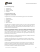
AT71-250 Transmitter Owner’s Manual AT71-250 General Description 1. INTRODUCTION AT71-250 is a 250W UHF ATSC Digital Broadcast Transmitter. It uses state-of-the-art technology of transmission of the digital signal for TV broadcast. It carries an intelligent digital control using microcontrollers, which allows for remote supervision in real time of all transmitter functionality.
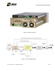
AT71-250 Transmitter Owner’s Manual Figure 2: AT72-250 - Rear View Figure 3 - AT71-250 - Block Diagram © Linear Industries, Inc.
AT71-250 Transmitter Owner’s Manual 2. Main Features Via the 4 lines x 40 columns display keypad located at the front panel it is possible to manage, configure all functions of the equipment and each one of the RF power drawer. Via the hyper-terminal it is also possible to manage, configure all of the functions of the transmitter. Digital Filter, type Finite Impulse Power (FIR) built-in at the 8VSB Modulator. Automatic non linear pre-correction. Automatic linear equalization.
AT71-250 Transmitter Owner’s Manual 3. AT71-250 stage-by-stage 1. 2. 3. 4. 1 Digital Exciter 1 RF power drawer Output FCC mask filter RF Sampler 4 General Description by stage 4.1 Digital Exciter, model AT8001. The digital exciter unit is also the control and monitoring system for the entire transmitter. 8VSB Modulador IF/UHF Up Converter Power Supply RF Amplifier Master Control Unit The AT8001 input is a single BNC connector that may receive either an ASI or SMPTE310M transport stream.
AT71-250 Transmitter Owner’s Manual The AT8001 is factory-set in one of four (4) optional versions. Depending upon the version it is possible set the operation with 2 types of non-linear pre-correction, mask filter equalization and/or ATSC set of 13 measurements on the RF signal demodulated. 4.2 300 watts RF power amplifier The main power amplification system is built with 1 RF power drawer.
AT71-250 Transmitter Owner’s Manual 4.5 Power Supplies All power transmitter supplies are full bridge switching power supplies. Each drawer includes a total of two power supplies, each with its own individual shut-down commands. These power supplies are in constant communication with its respective drawer control unit. The communication collects and distributes the voltage value (+50V nominal) and the electrical instantaneous current values in Ampere.
AT71-250 Transmitter Owner’s Manual Annex A – AT71-250 Operational Software 1. Introduction The DTV transmitter AT71-250 provisions: (a) measurements, (b) configurations, (c) alarms, and (d) remote control via microcontrollers. Below is a detailed description about the operational software (configuration and operation) system installed in the AT71-250, located within the AT8001 exciter. Figure 4 AT8001 AT8001 Exciter – Front Panel. 2. Digital Exciter – The Master Control Unit 6 1 4 5 2 3 2.
AT71-250 Transmitter Owner’s Manual (6) ESC – Cancel the selection and return to the previous screen. 2.2. LCD Display To browse over the LCD screen follow the instructions below: Move the arrow Up or Down to the item listed by pressing the (1) or (3) buttons. Main Menu : -> Setup Menu Measurements System Alarms/Log [0000] Remote Access Hit ENTER. Remarks: Please note that all screens are assigned a 4 digit number on the top-right of the LCD screen.
AT71-250 Transmitter Owner’s Manual After pressing any key on the keypad, the next screen that appears is: Main Menu : Setup Menu Measurements -> System Alarms/Log [0000] Remote Access (It is always possible to return to the initial LCD screen by pressing the ESC key) After 5 minutes the initial LCD screen is shown. 4.
AT71-250 Transmitter Owner’s Manual To access the menu above, see item 4.1 below: 4.1. Transmitter Power Measurements Main Menu : Setup Menu -> Measurements System Alarms/Log [0000] Remote Access Access Measurements Measurements : -> Power Transport Stream Drawer [2000] Exciter Power Supply Communication Status Power Supply Access Power and hit ENTER Hit key “3” to view the other screens that are part of this menu.
AT71-250 Transmitter Owner’s Manual 4.2.
AT71-250 Transmitter Owner’s Manual 4.3. RF Power Drawer Measurements For each RF Power Module it is possible to measure: (a) electrical current, (b) RF delivery power, (c) temperature. Hit the ESC key to return to the measurements screen menu, or return to the main menu screen and select measurements. Measurements : Power Transport Stream -> Drawer [2000] Exciter Power Supply Communication Status Power Supply Select Drawer and presses ENTER.
AT71-250 Transmitter Owner’s Manual Press ESC to return to the Drawer Measurements screen. Drawer Measurements : Power Current -> Temperature [2300] Select Temperature and press ENTER Drawer Temperature Measurements : [2330] Drawer : <__/__> Exciter: 0.0 °C ^°F^ Mod.1: 0.0 °C Mod.3: 0.0 °C Mod.2: 0.0 °C Mod.4: 0.0 °C Press ESC to return to the Measurements screen.
AT71-250 Transmitter Owner’s Manual 4.4 Communication among RF drawer From the LCD screen it is possible to conduct and view a diagnostic check of the communication link between the master control unit and each one of the RF power amplifier drawer. Press ESC, to the Main Menu screen, and then to the screen [2000] is reached, as below: Measurements : Power Transport Stream Drawer [2000] Exciter Power Supply -> Communication Status Power Supply Select Communication Status and press ENTER.
AT71-250 Transmitter Owner’s Manual Press the ESC key as many times as necessary to return to the main menu. 5. The alarm system An alarm is indicated by one of the 3 red LEDs located on the front panel of the digital exciter. The first LED alarm is for transport stream (TS) absence (SYNC. LOSS). The next LED alarm is for a current malfunction present on the equipment, and requires investigation, (see CURRENT ALARM). The third LED indicates a past alarm (see PAST ALARM).
AT71-250 Transmitter Owner’s Manual Press ESC to return to the System Alarms/ Log menu System Alarm/Log Current Alarms -> Alarm Log Drawer Alarms [3000] Clear Alarm Log Access the Alarm Log and press ENTER screen to find out if all existing alarms, current alarms, and also the past alarms.
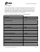
AT71-250 Transmitter Owner’s Manual Alarm Message Alarm Description Action Required After Alarm Ceases Sync Loss! Sync loss on the transport stream Alarm LED ON Alarm LED OFF Past alarm LED ON LO Lock Fail! Up-Converter LO PLL unlocked Clock Lock Fail! Fifo Overflow! +15V Fail! +8V Fail! +3V Fail! +27V Fail! Clock at Modulator unlocked Overflow on FIFO at the modulator Lack of +15V. Lack of +8V. Lack of +3V. Lack of +27V.
AT71-250 Transmitter Owner’s Manual Select Drawer Alarms and press ENTER. Drawer Alarms: -> Current Alarms Past Alarms [3300] Select Current Alarms and press ENTER to check current alarms Drawer : <__/__> Current Alarms: [3310] Alarm List Empty! Use the keys (4) or (2) to select one among many RF power drawer. Press key ESC to return to the previous screen, Drawer Alarms. On the screen [3320], press the keys (4) or (2) to select the drawer.
AT71-250 Transmitter Owner’s Manual 6.
AT71-250 Transmitter Owner’s Manual 6.2 Channel Frequency Setup The channel frequency change is illustrated here, but it is a parameter that cannot be changed by the operator in the field. It is factory adjusted only.
AT71-250 Transmitter Owner’s Manual Press ESC to return to the Frequency Setup screen.
AT71-250 Transmitter Owner’s Manual Press ESC to return to the Setup Menu. Setup Menu : Power Setup Frequency Setup Image Frequency Suppression [250] -> LO Leakage Suppression Pre-Correction Modulation Settings Time and Date Setup Password Setup Transmitter Setup Select LO Leakage Suppression and press ENTER. 7.4 LO Leakage Suppression An RF sample for monitoring purposes must be taken before the output mask filter.
AT71-250 Transmitter Owner’s Manual Select Pre-Correction and press ENTER Pre-Correction Setup: -> Linear Non-Linear [250] Select Linear and press ENTER Linear Pre-Correction: Linear Pre-correction: on/off [1510] Press ESC to return to Pre-correction Setup.
AT71-250 Transmitter Owner’s Manual Select Modulation Settings and press ENTER. Modulation Settings : Modulation : on/off Pilot Level offset : +0000 (-2.048 to 511) [1600] 7.7 Time and date configuration Press ESC up to Setup Menu screen.
AT71-250 Transmitter Owner’s Manual Press ESC key up to activate the SETUP MENU screen: Setup Menu : Power Setup Frequency Setup Image Frequency Suppression [250] LO Leakage Suppression Pre-Correction Modulation Settings Time and Date Setup -> Password Setup Transmitter Setup Access to the Password Setup Password Setup: -> Enable / choose new password Disable password [1800] To enable the password or set a new one, select Enable / choose new password.
AT71-250 Transmitter Owner’s Manual Using a PC local or remote access via Ethernet. 8.1 IP Configuration Start from the Main Menu Main Menu : Setup Menu Measurements System Alarms/Log [0000] -> Remote Access Select Remote Access and press ENTER Remote Access: -> IP Address Subnetwork Mask Gateway [3000] Select IP Address and press ENTER. IP Address: [4100] 192.168.100.018 Configure the IP using the keys 1 or 3 and 2 or 4. 8.
AT71-250 Transmitter Owner’s Manual 8.3 Gateway Configuration Press ESC up to the Remote Access screen Remote Access: IP Address Subnetwork Mask -> Gateway [3000] Access Gateway and press ENTER Gateway: [4300] [4300] 192.168.100.018 Configure the gateway address using 1 or 3 and 2 or 4. © Linear Industries, Inc.
AT71-250 Transmitter Owner’s Manual 300W UHF ATSC Power Amplifier Drawer Model GV4790 Functional Description The drawer GV 4790 is a UHF broadband power amplifier unit, air-cooled, designed to provide up to 300 Wrms ATSC. © Linear Industries, Inc.
AT71-250 Transmitter Owner’s Manual Below is the block diagram of the drawer. MOD 4782: RF Driver, +24Vdc. The RF Driver is a UHF broadband amplifier. (See the technical specs below). It is assembled in an aluminum basis that is silver finishing and firmly attached to the air cooled heat sink. The RF driver printed circuit board and the mechanical base of the transistors are welded on the same aluminum base plate.
AT71-250 Transmitter Owner’s Manual MOD 4782 - Technical specifications: Parameter Input Impedance Frequency Range Input Connector Input Return Loss Gain Phase Output Power Output Impedance Output Return Loss Output Connector Power Supply Specification 50 Ohms 470 to 806 MHz SMA-F >20dB 24dB to 30dB 70° to 120° at 570MHz Up to 50W (ATSC) 50 Ohms >20dB SMA-F +24V MOD 4792: UHF divider 1:2 This module is a broadband passive design. No adjustment is required. Its divide equally the incoming RF signal in 2.
AT71-250 Transmitter Owner’s Manual MOD 4791: 2:1 UHF Combiner The UHF 2:1 combiner is a module operates over the all UHF band from 470 to 806 MHz, without adjustments. Moreover, it has an internal low pass filter mainly designed to reduce the 3rd harmonic components generated by the amplification chain. It also has a power level detector circuit, reading the values of direct (FWD) and reverse power (REF).
AT71-250 Transmitter Owner’s Manual The 4810 module is an AC / DC converter having power factor correction (PFC) with input of 180VAC to 240VAC and 370VDC output referenced to AC mains ground (not isolated). The configuration used by this converter topology is named Boost Regulator. This configuration uses one MOSFET, one diode, one coil operation under a 100 KHz switching frequency.
AT71-250 Transmitter Owner’s Manual Technical Specifications: Parameter Supply Voltage Consumption Analog Inputs Digital Outputs Analog Outputs Digital Inputs Specification +15V 60mA 22 24 0 6 MOD CIM 3765: Interface USB The USB interface board is located on the rear panel of the drawer. It is a USB connection between the control board digital power drawer and a computer. On this board is also mounted bi-color LED signaling drawer power.
AT71-250 Transmitter Owner’s Manual MOD 3886 - Technical Specifications: Parameter Supply Voltage Switching Frequency Nominal Output Voltage Specification +50V 125kHz +50Vdc and +24Vdc MOD CIM 3917: Power Supply for the auxiliary bank of fans This module is a DC / DC converter of +50 Vdc to +24 Vdc, which feeds the bank of auxiliary fans of the drawer GV 4790. It can provide up to 3A.