
User's Manual

AT71-250 Transmitter Owner’s Manual
© Linear Industries, Inc. All Rights Reserved 10/38
4
4
.
.
5
5
P
P
o
o
w
w
e
e
r
r
S
S
u
u
p
p
p
p
l
l
i
i
e
e
s
s
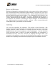
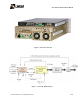
All power transmitter supplies are full bridge switching power supplies. Each drawer includes
a total of two power supplies, each with its own individual shut-down commands. These
power supplies are in constant communication with its respective drawer control unit. The
communication collects and distributes the voltage value (+50V nominal) and the electrical
instantaneous current values in Ampere. The normal mains value for all power supplies is
208Vac. The three different models present on this transmitter are:
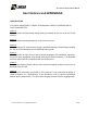
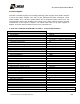
5. AT71-250 - 250W UHF ATSC/8VSB Transmitter - Technical Specifications
Electrical
Main
120 VAC, bi phase, 50-60 Hz.
Consumption
1080 W
Power Factor Correction, FPC.
Included
Signal Input
Transport Stream Input
ATSC/MPEG2, compliant to SMPTE310M or
ASI
Input Data Rate
19.39 Mbps (SMPTE / 310M) / 270Mbps (ASI)
External Reference Signal
10MHz. (0 to +10 dBm).
Input Connector
75Ω (BNC),
Reference Input Connector
50Ω (BNC),
RF
Modulation Mode
8VSB.
IF
18.833916 MHz.
Channel Bandwidth
6MHz.
Test Signal
PRBS
Frequency Range
UHF. C14 to Ch59, (4 bands).
Frequency Step
1 Hz. ± 220kHz
Symbol Rate
10.76 MSymbol/sec.
Digital/Analog Converter
16 bit
Both Linear and Non-Linear Pre-Correction at factory
Included
Pilot frequency stability overall
±0.3 ppm
Peak to peak frequency response
≤ 0.2 dB
Peak to peak group delay response
≤ 20 ns.
Phase noise
≤ -104 dBc/Hz @ 20kHz offset.
Conducted spurious and harmonics
< -60 dBc, FCC 47 Part 74.
Radiated spurious and harmonics
< -80 dBc, FCC 47 Part 74.
MER (Modulation Error Rate)
≥ 33 dB (transmitter output) typical.
RF output connector
N
Output sample connector
N
Communication
Hyper-terminal
RS232 (DB-9)
Mechanical
Dimensions
7.13” (H) X 12” (W) X 9” (D)
Weight
NET: 100 lbs