
User's Manual
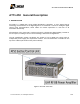

AT71-250 Transmitter Owner’s Manual
© Linear Industries, Inc. All Rights Reserved 7/38
2. Main Features
Via the 4 lines x 40 columns display keypad located at the front panel it is possible to
manage, configure all functions of the equipment and each one of the RF power
drawer.
Via the hyper-terminal it is also possible to manage, configure all of the functions of
the transmitter.
Digital Filter, type Finite Impulse Power (FIR) built-in at the 8VSB Modulator.
Automatic non linear pre-correction.
Automatic linear equalization.
Built in oscillators synthesized via serial-PLL, locked at a 10MHz OCXO reference or
external equivalent reference, e.g. GPS signal.
The UHF RF power amplifier was implemented with LDMOS transistors, operating
highly linearly at higher gain under high efficiency and absolute controlled thermal
conditions.
Automatic control over the quiescent operational electrical current value on the RF
main power transistors, under temperature variations.
Self-protection against over-current on the RF main power amplifiers.
Each RF power module carries its own +50 volts full bridge type switching power
supply.
Automatic Level Control (ALC) control, which keeps the RF on-channel output level
constant, even with a +3 dB overall system gain variation.
System fault indication shown on the front panel, including current and past alarms log.
Low noise, variable speed fans for the air cooling system.
Modular design, built with SMD (Surface Mounted Devices), easing the maintenance
and service.
Outstanding overall field system performance.
19” rack cabinet.