
User's Manual

AT71-250 Transmitter Owner’s Manual
© Linear Industries, Inc. All Rights Reserved 8/38
3. AT71-250 stage-by-stage
1. 1 Digital Exciter
2. 1 RF power drawer
3. Output FCC mask filter
4. RF Sampler
4 General Description by stage
4
4
.
.
1
1
D
D
i
i
g
g
i
i
t
t
a
a
l
l
E
E
x
x
c
c
i
i
t
t
e
e
r
r
,
,
m
m
o
o
d
d
e
e
l
l
A
A
T
T
8
8
0
0
0
0
1
1
.
.
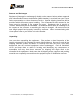
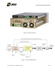
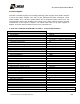
The digital exciter unit is also the control and monitoring system for the entire transmitter.
8VSB Modulador
IF/UHF Up Converter
Power Supply
RF Amplifier
Master Control Unit
The AT8001 input is a single BNC connector that may receive either an ASI or SMPTE310M
transport stream. The modulation process follows ATSC A/53E recommendation, and is a
complex modulation process generating identical phase-modulated orthogonal IF carriers, (I)
and (Q) at frequency of 18.833916 MHz.
Both (I) and (Q) modulated carriers are routed into the IF/UHF up-converter. The local
oscillator is a synthesized time-based PLL via an internal OCXO (Oven Controlled Crystal
Oscillator) at 10MHz reference, or an equivalent one external reference, e.g. a GPS signal.
The on-channel modulated signal is routed to the RF amplifier, a class A highly linear
amplifier with enough head room to accommodate future signal amplitude expansion during
the non-linear pre-correction process.
The AT8001 output delivers a variable 100mW max RF output level, (+20dBm) at the desired
UHF channel, driving the RF power amplifiers line-up.
The Master Control Unit (MCU) of the unit is embedded in the AT8001. The MCU interacts
with all functionality present within the equipment. It further interfaces externally via a keypad
and an LCD display.
The MCU receives information proceeding from several modules, as the DTV modulator, Up-
Converter, RF amplifiers, RF samples and the administration of passwords. Via keypad it is
possible to read and program the power level delivered by the transmitter. Major changes on
the transmitter configuration are possible with factory assistance.