
User's Manual

AT71-250 Transmitter Owner’s Manual
© Linear Industries, Inc. All Rights Reserved 9/38
The AT8001 is factory-set in one of four (4) optional versions. Depending upon the version it
is possible set the operation with 2 types of non-linear pre-correction, mask filter equalization
and/or ATSC set of 13 measurements on the RF signal demodulated.
4
4
.
.
2
2
3
3
0
0
0
0
w
w
a
a
t
t
t
t
s
s
R
R
F
F
p
p
o
o
w
w
e
e
r
r
a
a
m
m
p
p
l
l
i
i
f
f
i
i
e
e
r
r
The main power amplification system is built with 1 RF power drawer. The drawer carries a
set of 3 fans, switching power supply, 3 RF pallets, an intermediate power amplifier, a
removable (plug-in) control system based on microcontrollers and includes a hyper-terminal
interface.
The use of the hyper-terminal interface allows the operator to adjust the quiescent RF
transistor’s current via software. It is also possible to retrieve data information regarding RF
transistor current variations as a function of the temperature variation. Further, it is possible to
collect valuable system information related with the RF drawer serial number, embedded
software name and version, direct and reverse RF power readings, one-by-one RF transistor
current readings, and detailed descriptions about current and past alarms.
4
4
.
.
3
3
R
R
F
F
P
P
o
o
w
w
e
e
r
r
S
S
e
e
n
n
s
s
o
o
r
r
.
.
R
R
F
F
s
s
a
a
m
m
p
p
l
l
e
e
.
.
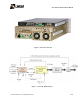
RF samples associated with the direct and reverse RF power are detected with this unit, and
converted to proportional DC readings. These 2 DC levels are routed to the MCU located in
the exciter where they are processed and displayed on the LCD screen. The processing of
this analog information manages the RF power delivered by the transmitter, increasing or
reducing it as part of the automatic level control (ALC) and is a part of the automatic
linearization/equalization of the transmitter. The RF samples are available in two points in the
RF path (line-up), BEFORE and AFTER the RF output filter. The second set of RF samples is
the last element on the transmitter line-up, directly connected to the output transmission and
antenna system.
4
4
.
.
4
4
O
O
u
u
t
t
p
p
u
u
t
t
M
M
a
a
s
s
k
k
F
F
i
i
l
l
t
t
e
e
r
r
The UHF RF channel output filter is a tunable band-pass six pole elliptical synthesis type filter.
This filter reduces the unwanted spurious and harmonics signals inherent in the RF
amplification process. The filter bandwidth and attenuation specifications are two important
components that help the transmitter to meet the FCC an ATSC A/53E specification
recommendation.