
User's Manual


AT7120 Owner Manual Rev. 1.1 – March 2009 8/76
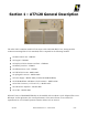
Module 4549
8VSB Modulator
The 8VSB modulator automatically recognizes the incoming transport stream as either SMPTE310M or
ASI. The transport stream input utilizes the BNC connector located on the rear panel of the unit. The
modulated output signal of this module is composed by two IF orthogonal carriers termed; signals (I)
and (Q). The central frequency of the 8VSB modulated IF signal is 18.83339MHz. The signal
processing and modulation performed on this module follows the ATSC recommendation A/53 E.
This module also performs the non-linear corrections that might be necessary to enhance the equipment
efficiency to meet FCC spurious emissions requirements. In this case, an RF output filter is required.
The recommended linear equalization is also automatically performed in this module.
Master Clock
The master clock unit generates signals utilizing a Voltage Controlled Oscillator and Phase Locked
Loop at 172.16MHz. The PLL is locked at 10MHz reference, externally or internally generated. This
signal provides the time base for the 8VSB modulator.
Module 4492
IF to UHF up-Converter
The IF carries the orthogonal (I) and (Q) signals generated in module 4549, (8VSB Modulator), which is
then routed to the up-converter module. The output signal of this module is set on the FCC/UHF
operational 6MHz channel of the transmitter AT7120.
Inside the converter the modulated IF band is mixed with the continuous wave local oscillator LO. As a
result of this mixing, the IF translation to the UHF band is performed. The LO is a free oscillator, that
has its frequency locked via PLL. The LO/PLL is generated by a 10MHz OCXO (oven controlled
crystal oscillator), or provided by an external reference signal.
Module 4281
10MHz reference automatic switching
Both circuits; the 8VSB modulator and the up-converter, share the same reference signal source. The use
of the same reference signal creates perfect synchronization and stability during the DTV transmission
process. The internal 10MHz signal is obtained from an OCXO oscillator with a stability of 0.3ppm. An
external 10MHz signal can be used as the reference signal; a GPS signal for instance. The external
reference input is a BNC connector located on the rear panel of the unit. In the absence of this external
source, the unit automatically utilizes the internal 10MHz source generated by the OCXO.